Transmitter Hardware
The normal hardware section will be split into two parts. The first part will show you how the transmitter circuit was built on a single breadboard. No tricks, we're just following the schematic here. The second part will show you how the receiver was build, again on a single breadboard, following the schematic.
Xbee + SIPs
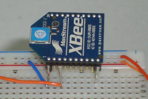
For whatever reason, the Xbee module doesn't used standard 2.54mm (0.1") pitch pins, so it doesn't fit into a breadboard like an IC. To solve this minor issue, I attached 3 SIPs to the Power, Ground and Din pins as you can see in the picture above. After doing that, the Xbee module fits nicely into the breadboard.
Building The Wireless Xbee Servo Controller Transmitter
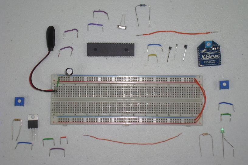
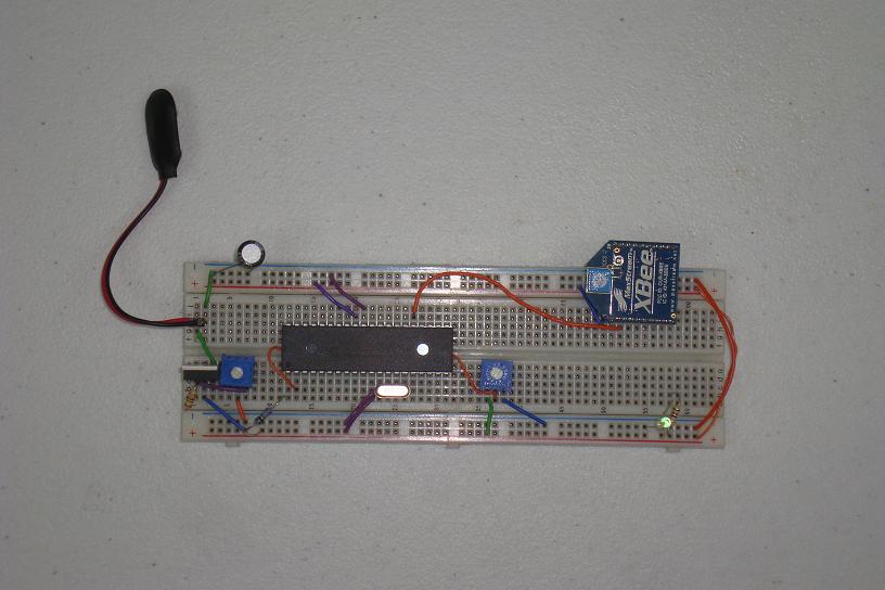
Below, I'll go step by step starting with all the parts laid out and then connect them together on the breadboard section by section until the transmitter is complete. In the pictures below you can see all the parts used for the transmitter:
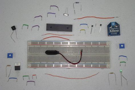
·First the 9v connector is added to the board.

·Next we connect the +3.3v Power Circuit via the LM317.
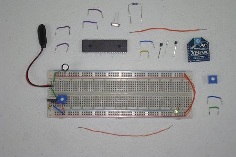
·The basic PIC circuit comes next. PIC18LF4520 + 20 MHz Crystal.
·Here we add the input trimpot circuitry.

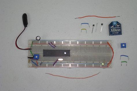
·Lastly, the Xbee is wired up to power, ground and the PIC.
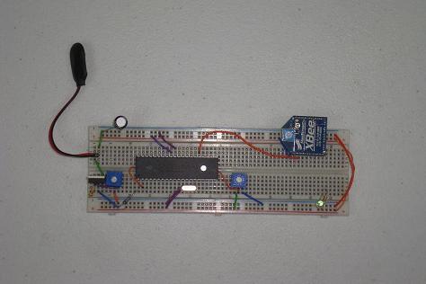
·The transmitter is complete, it just needs some software and its ready to go. Now let's take a look at the receiver hardware.
The normal hardware section will be split into two parts. The first part will show you how the transmitter circuit was built on a single breadboard. No tricks, we're just following the schematic here. The second part will show you how the receiver was build, again on a single breadboard, following the schematic.
Xbee + SIPs
For whatever reason, the Xbee module doesn't used standard 2.54mm (0.1") pitch pins, so it doesn't fit into a breadboard like an IC. To solve this minor issue, I attached 3 SIPs to the Power, Ground and Din pins as you can see in the picture above. After doing that, the Xbee module fits nicely into the breadboard.
Building The Wireless Xbee Servo Controller Transmitter
Below, I'll go step by step starting with all the parts laid out and then connect them together on the breadboard section by section until the transmitter is complete. In the pictures below you can see all the parts used for the transmitter:

·First the 9v connector is added to the board.
·Next we connect the +3.3v Power Circuit via the LM317.
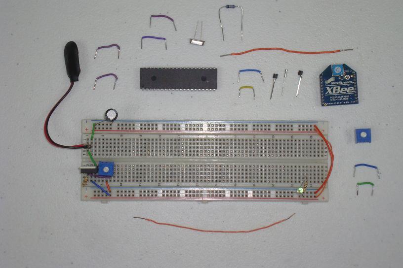
·The basic PIC circuit comes next. PIC18LF4520 + 20 MHz Crystal.

·Here we add the input trimpot circuitry.
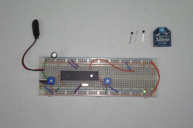
·Lastly, the Xbee is wired up to power, ground and the PIC.
·The transmitter is complete, it just needs some software and its ready to go. Now let's take a look at the receiver hardware.