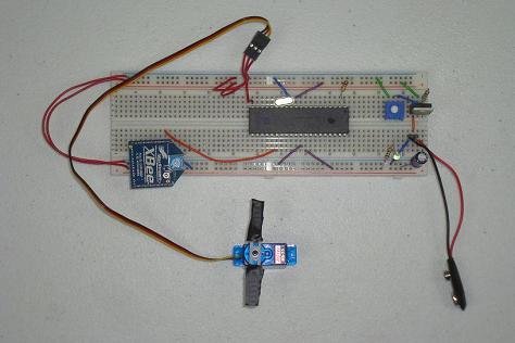
Receiver Hardware
The second part of the hardware we need to put together is the receiver portion of the schematic. This hardware will receive the wireless transmission, decode and tell the servo motor where and how to move.
This 'tiny' development board packs a large punch because of all the extra features it has. RAM, ROM, Accelerometer, Tons of I/O, LEDs, Push Buttons and a gigantic FPGA to go with it all.
Building The Wireless Xbee Servo Controller Receiver
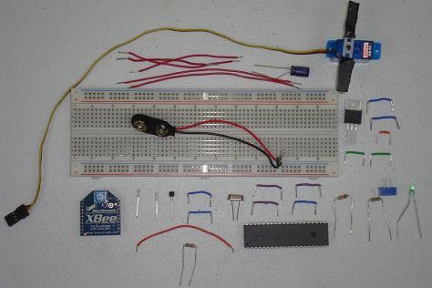
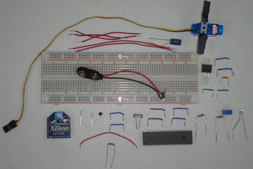
Below you can see a picture of all the parts used to build the receiver portion of the circuit. So let's get started building it!
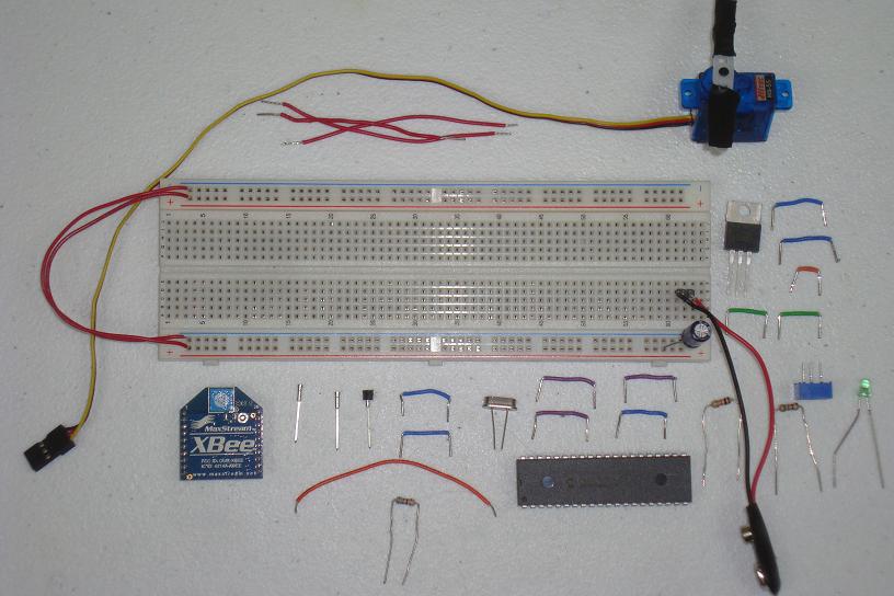
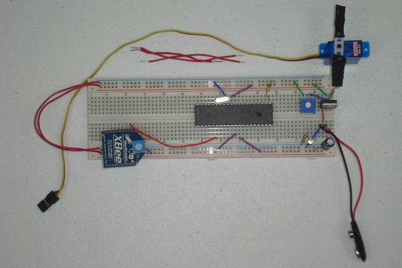
·First the 9v connector is put into the breadboard.
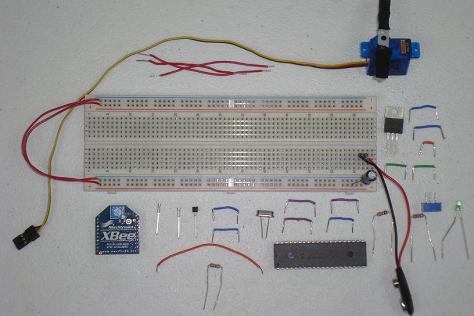
·Next, the power circuit is assembled to output +3.3v.
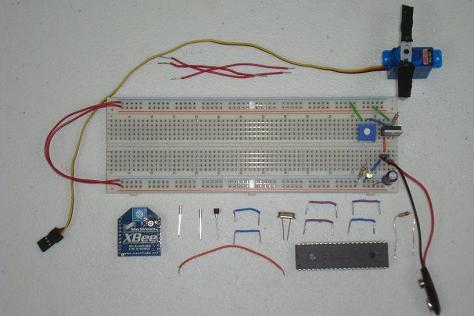
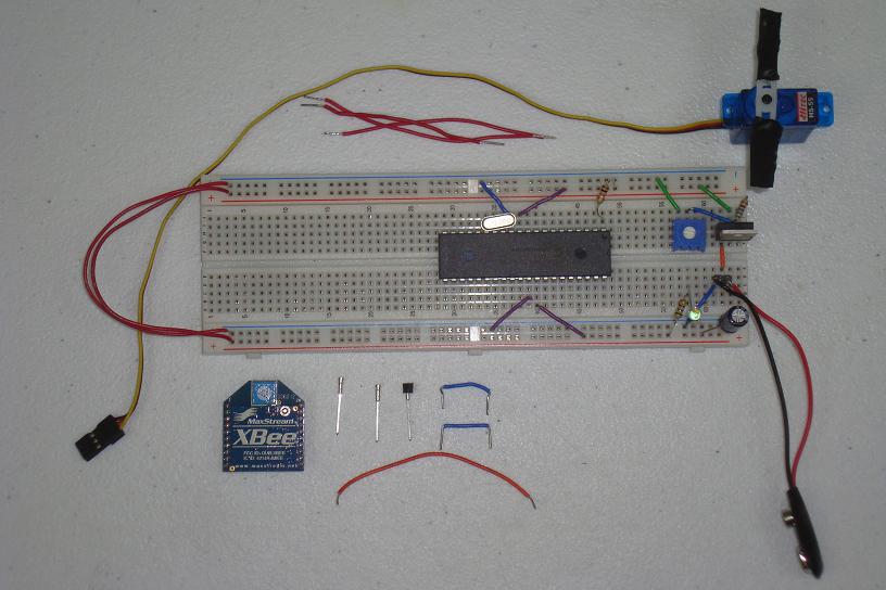
·The PIC circuit, 18LF4520 + 20 MHz Crystal, is added to the board.

·The Xbee module's 3 pins: Power, Ground, Dout are connected.
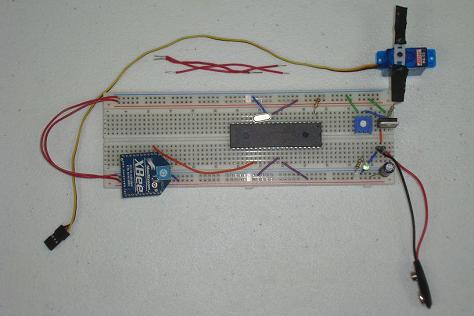
·Lastly, the servo motor is connected to Power, Ground and Signal.
·Now that both the transmitter and receiver have been assembled, let's take a look at the software for each PIC and get it uploaded to the PICs.
The second part of the hardware we need to put together is the receiver portion of the schematic. This hardware will receive the wireless transmission, decode and tell the servo motor where and how to move.
This 'tiny' development board packs a large punch because of all the extra features it has. RAM, ROM, Accelerometer, Tons of I/O, LEDs, Push Buttons and a gigantic FPGA to go with it all.
Building The Wireless Xbee Servo Controller Receiver
Below you can see a picture of all the parts used to build the receiver portion of the circuit. So let's get started building it!
·First the 9v connector is put into the breadboard.
·Next, the power circuit is assembled to output +3.3v.

·The PIC circuit, 18LF4520 + 20 MHz Crystal, is added to the board.
·The Xbee module's 3 pins: Power, Ground, Dout are connected.
·Lastly, the servo motor is connected to Power, Ground and Signal.

·Now that both the transmitter and receiver have been assembled, let's take a look at the software for each PIC and get it uploaded to the PICs.