Servo Motor Theory
The signal that we need to create inorder to control the servos is called a Pulse With Modulation signal or PWM for short. The general requirements are:
Frequency: 50Hz
Up-time: 0.9mS ~> 2.1mS
Down-time: 19.1mS ~> 17.9mS
At first glance these definitions & numbers might make little or no sense. So lets look at a simple PWM wave at 50Hz.
So a PWM wave is just a signal that changes between 0 volts & 5 volts (digital logic 0 and 1). We see that the wave is symmetrical; uptime is 10mS & downtime is 10mS which when added together give us the period (10mS + 10mS = 20mS).
Xbee Modules @ 9600 Baud
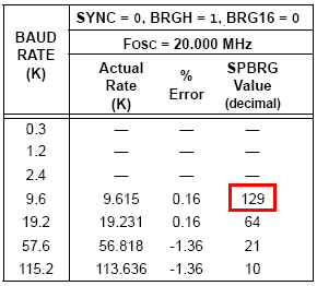
In order for the PIC's serial communication module (USART) to send serial data at the correct speed, it uses a 'counter' to know when to send the next bit. A quick look at the PIC 18LF4520's datasheet shows us a table that correlates to our 20 MHz oscillator speed and shows us what value to set the 'counter' to, in our case it is: 129.
The datasheet also has the exact formula for calculating this number, but it's far easier to look it up in the tables they have if you're using a standard oscillator frequency.
The signal that we need to create inorder to control the servos is called a Pulse With Modulation signal or PWM for short. The general requirements are:
Frequency: 50Hz
Up-time: 0.9mS ~> 2.1mS
Down-time: 19.1mS ~> 17.9mS
At first glance these definitions & numbers might make little or no sense. So lets look at a simple PWM wave at 50Hz.
So a PWM wave is just a signal that changes between 0 volts & 5 volts (digital logic 0 and 1). We see that the wave is symmetrical; uptime is 10mS & downtime is 10mS which when added together give us the period (10mS + 10mS = 20mS).
Xbee Modules @ 9600 Baud
In order for the PIC's serial communication module (USART) to send serial data at the correct speed, it uses a 'counter' to know when to send the next bit. A quick look at the PIC 18LF4520's datasheet shows us a table that correlates to our 20 MHz oscillator speed and shows us what value to set the 'counter' to, in our case it is: 129.
The datasheet also has the exact formula for calculating this number, but it's far easier to look it up in the tables they have if you're using a standard oscillator frequency.