Schematic Overview
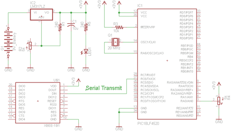
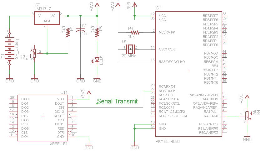
There are two schematics that we'll look at to see how to build this transmitter/receiver system. The first one is the transmitter, with a variable trimpot input into RA0. The trimpot value will be sent out of the Tx pin of the PIC and to the Din pin of the Xbee module to send the signal wirelessly.
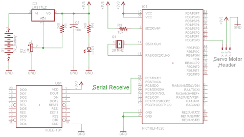
The receiver circuit, will receieve the transmitted signal through the Xbee module, out of the Dout pin and to the PIC's Rx pin. The receiving PIC will then translate the data to movement coordinates for the servo motor.
Cadsoft Eagle Project Files: Xbee Wireless Servo Control
Transmitter Schematic
View Full Schematic
" Trimpot Input Into The PIC
The input we will give to the PIC's will come from a standard trimpot's output. The trimpot is tied to power and ground, with the middle pin being a variable voltage send to the PIC's A/D converter on pin RA0.
"Xbee Module Wireless Output
The PIC will then translate this input to an integer of value 0-50 and send it via the PIC's serial communication module at 9600 BPS to the Xbee's Din pin.
Receiver Schematic
View Full Schematic
"Servo Motor Output
After the serial data is receieved by the PIC, it will put the dynamic integer value into the the delay cycle that is creating a PWM output to control the servo motor. Each specific value of 0 to 50 correlates to a specific location that the motor can move to.
"Xbee Module Wireless Input
The Xbee receiver will automatically connect with the transmitter and begin receiving data. All data will be receiving and output via the Dout pin on the Xbee module. The Dout pin is conneceted directly to the PIC's Rx pin so that the PIC can catch the data.
There are two schematics that we'll look at to see how to build this transmitter/receiver system. The first one is the transmitter, with a variable trimpot input into RA0. The trimpot value will be sent out of the Tx pin of the PIC and to the Din pin of the Xbee module to send the signal wirelessly.
The receiver circuit, will receieve the transmitted signal through the Xbee module, out of the Dout pin and to the PIC's Rx pin. The receiving PIC will then translate the data to movement coordinates for the servo motor.
Transmitter Schematic
View Full Schematic
" Trimpot Input Into The PIC
The input we will give to the PIC's will come from a standard trimpot's output. The trimpot is tied to power and ground, with the middle pin being a variable voltage send to the PIC's A/D converter on pin RA0.
"Xbee Module Wireless Output
The PIC will then translate this input to an integer of value 0-50 and send it via the PIC's serial communication module at 9600 BPS to the Xbee's Din pin.
Receiver Schematic

View Full Schematic
"Servo Motor Output
After the serial data is receieved by the PIC, it will put the dynamic integer value into the the delay cycle that is creating a PWM output to control the servo motor. Each specific value of 0 to 50 correlates to a specific location that the motor can move to.
"Xbee Module Wireless Input
The Xbee receiver will automatically connect with the transmitter and begin receiving data. All data will be receiving and output via the Dout pin on the Xbee module. The Dout pin is conneceted directly to the PIC's Rx pin so that the PIC can catch the data.