Hardware Receiver Design
The transmitter was not a difficult thing to build and luckily the receiver is just about as simple. It only has 1 extra step.
Putting Everything Together
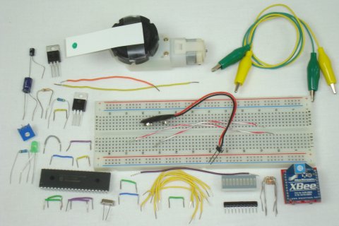
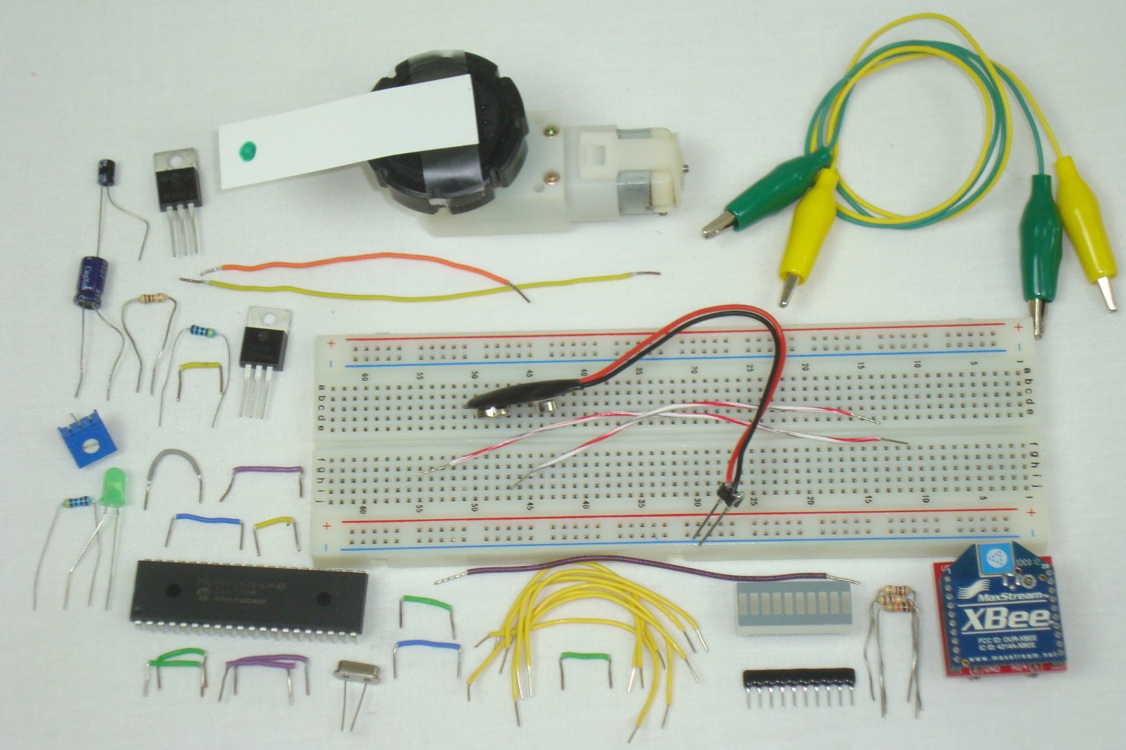
Again, double check you have all the parts seen in the schematic and get ready to start building! The first step is always gathering the parts together so you can start building, and below you can see all the parts.
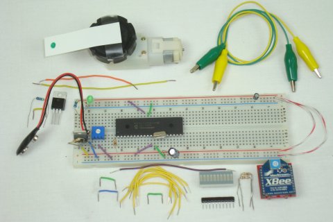
The first connections are all the +3.3v power supply connections, capacitors and power LED.

Next, the basic PIC circuit is added to the breadboard, with power, ground, crystal and 10kΩ connected to the PIC.
Now, the XBee wireless module is connected to power, ground and the PIC's Tx output.
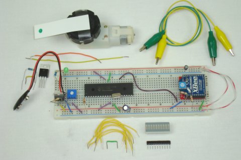
Next, the LED Bar and resistor network are connected to the PIC's PORTD
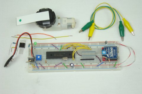
The final step is adding the motor control circuit and connecting the motor to it with some alligator clips.
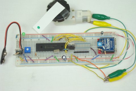
That's it! Now let's take a look at the PIC's firmware/software to see how we'll capture input and turn it into nifty motor controlling output!
The transmitter was not a difficult thing to build and luckily the receiver is just about as simple. It only has 1 extra step.
Putting Everything Together
Again, double check you have all the parts seen in the schematic and get ready to start building! The first step is always gathering the parts together so you can start building, and below you can see all the parts.
The first connections are all the +3.3v power supply connections, capacitors and power LED.
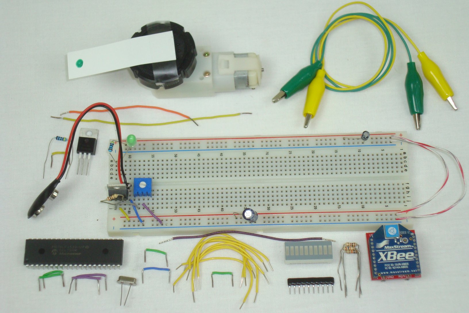
Next, the basic PIC circuit is added to the breadboard, with power, ground, crystal and 10kΩ connected to the PIC.

Now, the XBee wireless module is connected to power, ground and the PIC's Tx output.
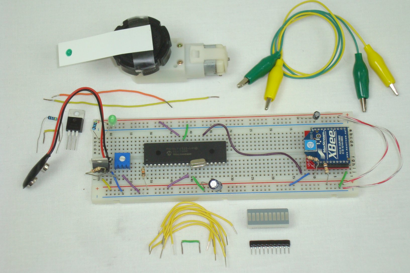
Next, the LED Bar and resistor network are connected to the PIC's PORTD

The final step is adding the motor control circuit and connecting the motor to it with some alligator clips.

That's it! Now let's take a look at the PIC's firmware/software to see how we'll capture input and turn it into nifty motor controlling output!