Finishing The Kit Assembly
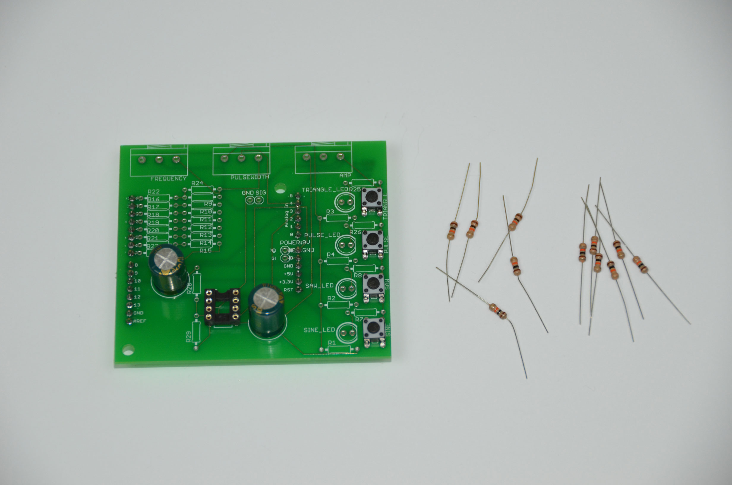
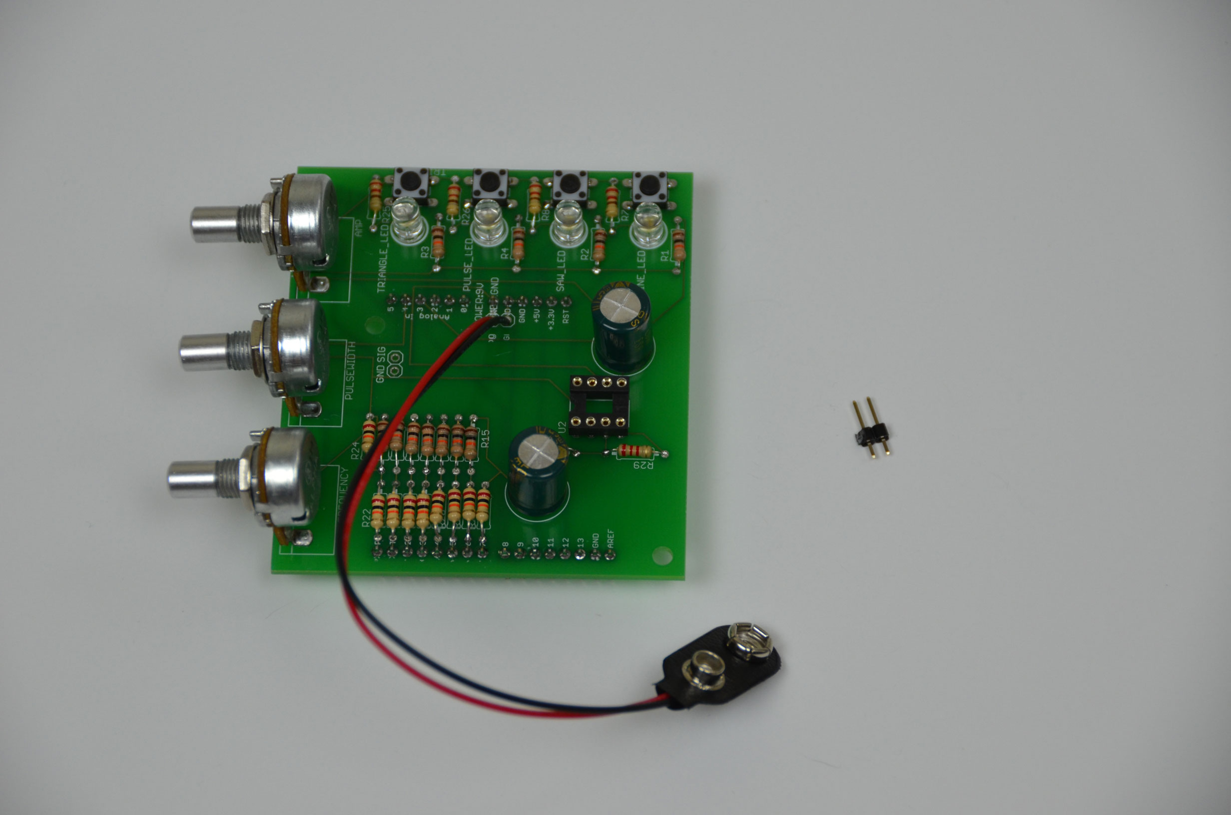
Now we'll finish off the assmebly process by soldering in the resistor ladder, trimpots, power plug and adding the knobs. First, we'll start the resistor ladder. Be sure to read and follow the instructions carefully and make sure you're using the correct colored resistors.

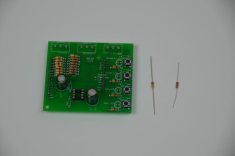
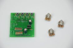
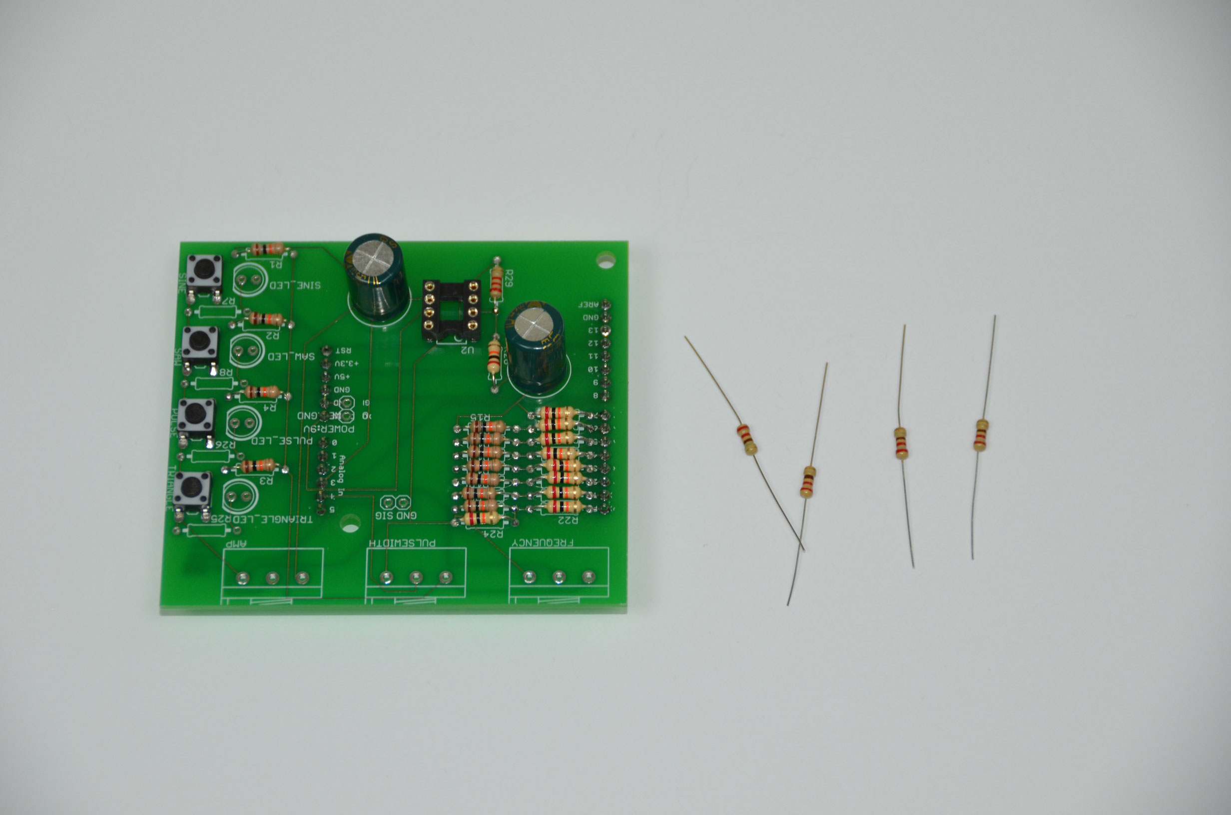
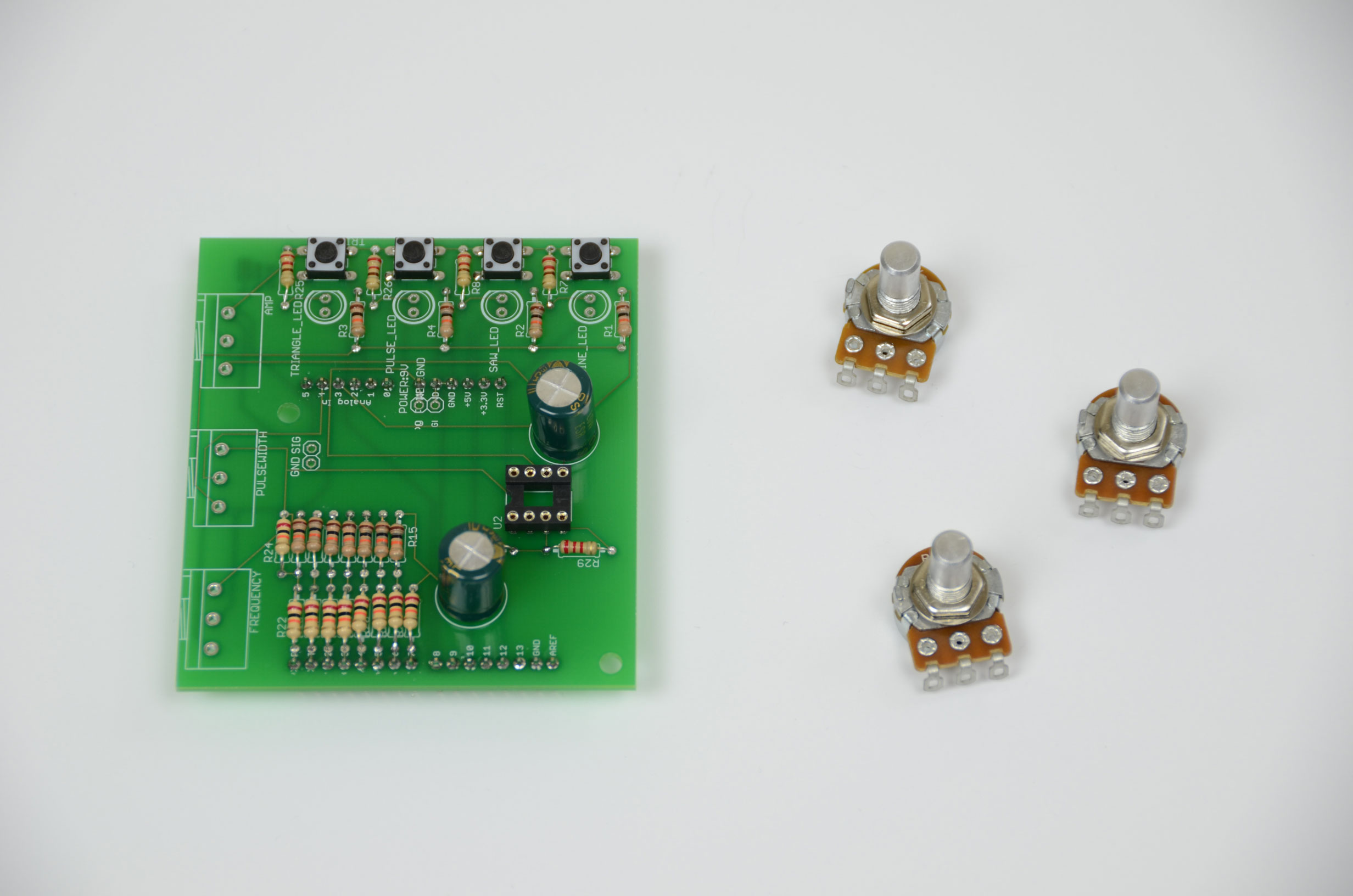
With the resistor ladder finished, we'll add some current limiting resistors before the LEDs and the trimpots will need to be soldered down. If you solder down the trimpots as I have, you'll want to use a lot of solder to make sure they are firmly attached to the PCB. Great care must be taken afterward because there isn't much support for them, they just kind of float in the air.

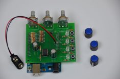
We're down to the final few steps. The 9v battery connector wires are soldered into the PCB directly in the middle of the board. Then we'll take some of the leftover header pins and solder two of them to the SIG and GND output connections of the waveform generator.


The last step is to plug the board into the Arduino and see how the shield fits in perfectly still and then to add on the nicely colored knobs which will control amplitude, frequency and duty cycle parameters.
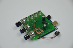
As far as assembly goes, this is a really fun kit to put together. The difficulty is medium, but it's definitely do-able by anyone, even beginners. The harder part comes next when we need to load the firmware program onto the Arduino. Let's go!
Now we'll finish off the assmebly process by soldering in the resistor ladder, trimpots, power plug and adding the knobs. First, we'll start the resistor ladder. Be sure to read and follow the instructions carefully and make sure you're using the correct colored resistors.

With the resistor ladder finished, we'll add some current limiting resistors before the LEDs and the trimpots will need to be soldered down. If you solder down the trimpots as I have, you'll want to use a lot of solder to make sure they are firmly attached to the PCB. Great care must be taken afterward because there isn't much support for them, they just kind of float in the air.
We're down to the final few steps. The 9v battery connector wires are soldered into the PCB directly in the middle of the board. Then we'll take some of the leftover header pins and solder two of them to the SIG and GND output connections of the waveform generator.
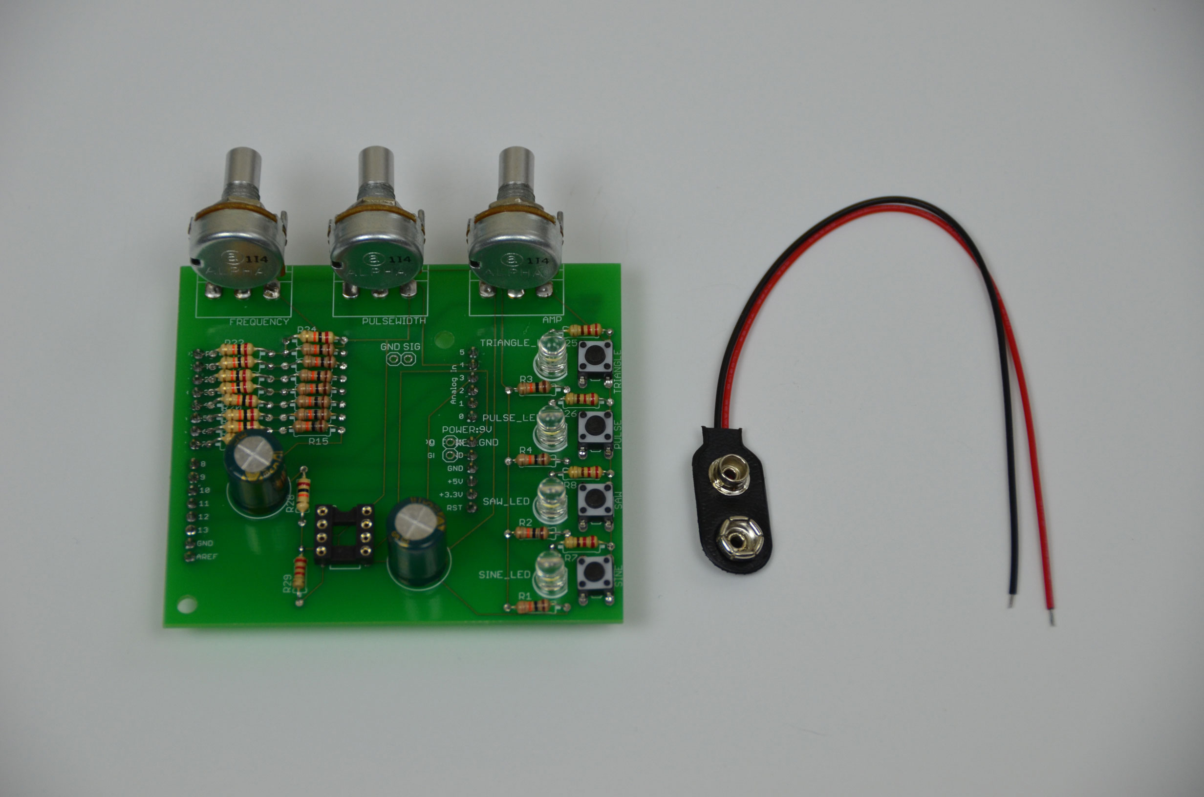
The last step is to plug the board into the Arduino and see how the shield fits in perfectly still and then to add on the nicely colored knobs which will control amplitude, frequency and duty cycle parameters.


As far as assembly goes, this is a really fun kit to put together. The difficulty is medium, but it's definitely do-able by anyone, even beginners. The harder part comes next when we need to load the firmware program onto the Arduino. Let's go!