Starting The Kit Assembly
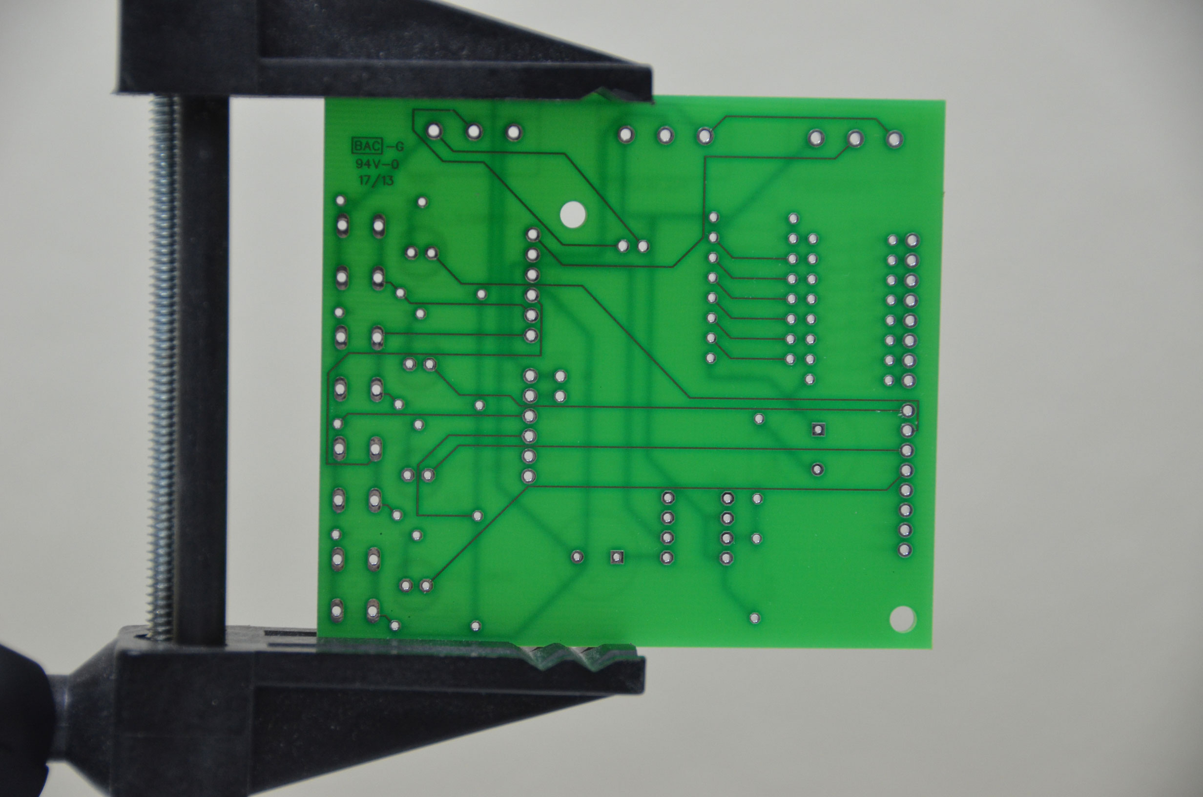
The PCB, for the Arduino Waveform Generator kit can be seen in the pictures below, means you need only solder the right parts into the right locations. With the white silkscreen, it is obvious where each part goes making assembly a breeze.

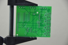
The 8x8x8 LED Cube kit required you to figure out the layout and wiring of the circuit board using a protoboard which was a headache and a lot of extra effort. But as you can see, the PCB has that taken care of already, so let's get to soldering!
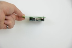
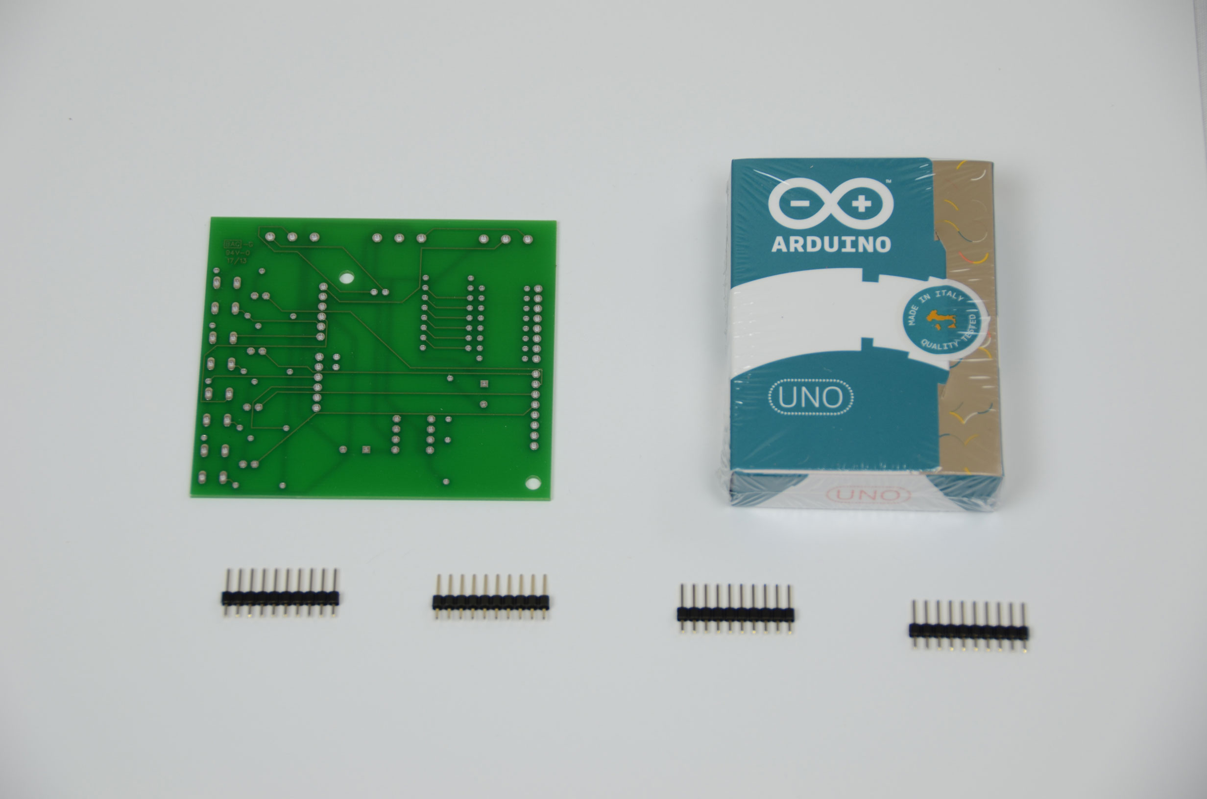
To start things off, we'll cut the header pins so that they fit into the Arduino specific holes. Solder the outer two pins of the header first so that you can get each header placed properly and evenly.


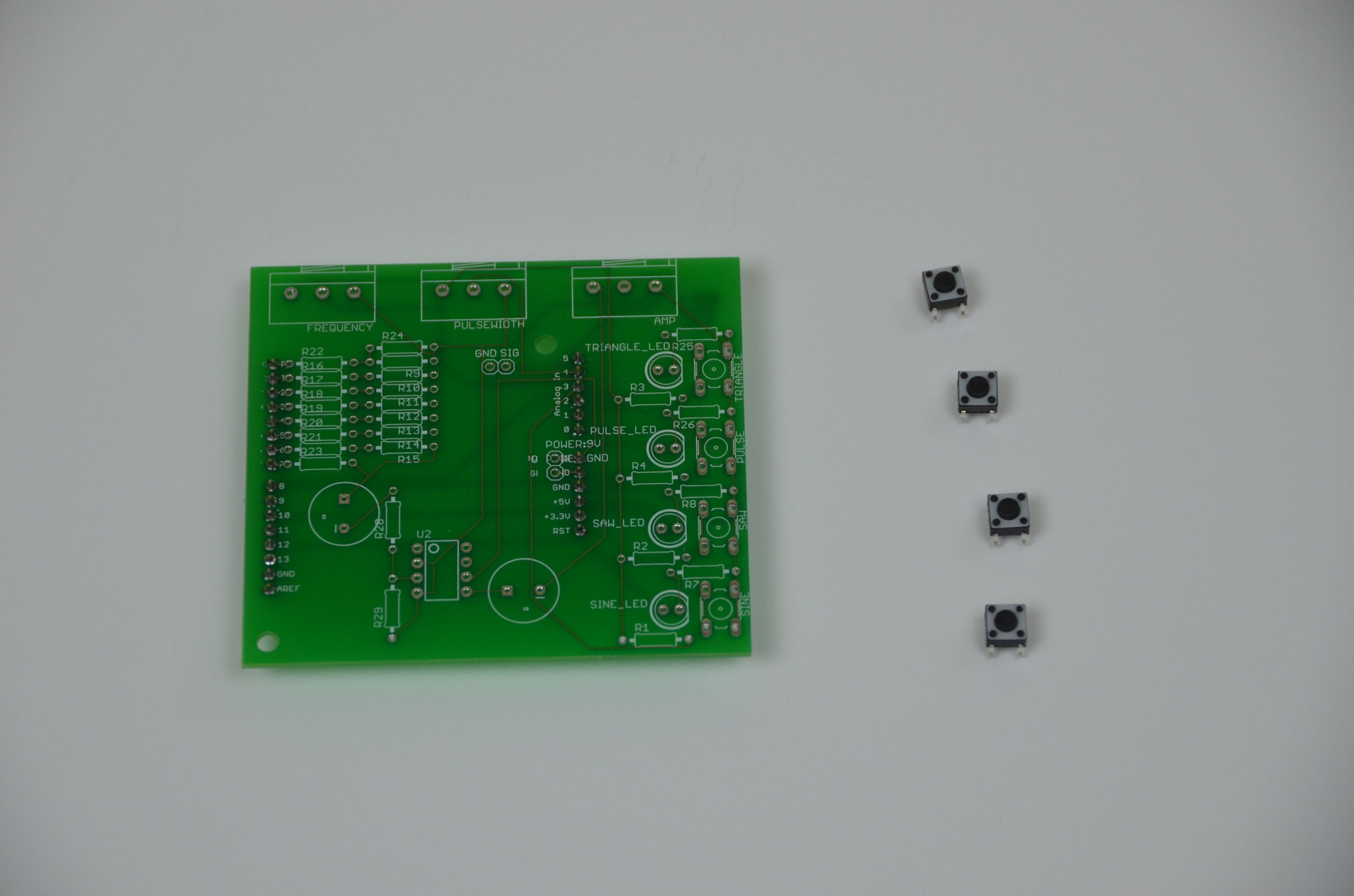
Once the header pins are all soldered into place, the PCB should fit into an Arduino UNO with no effort. You can see an example image below of how the PCB connects to an Arduino. However, we're not even close to finished. Next we'll solder on the 4 tactile push buttons.

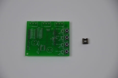
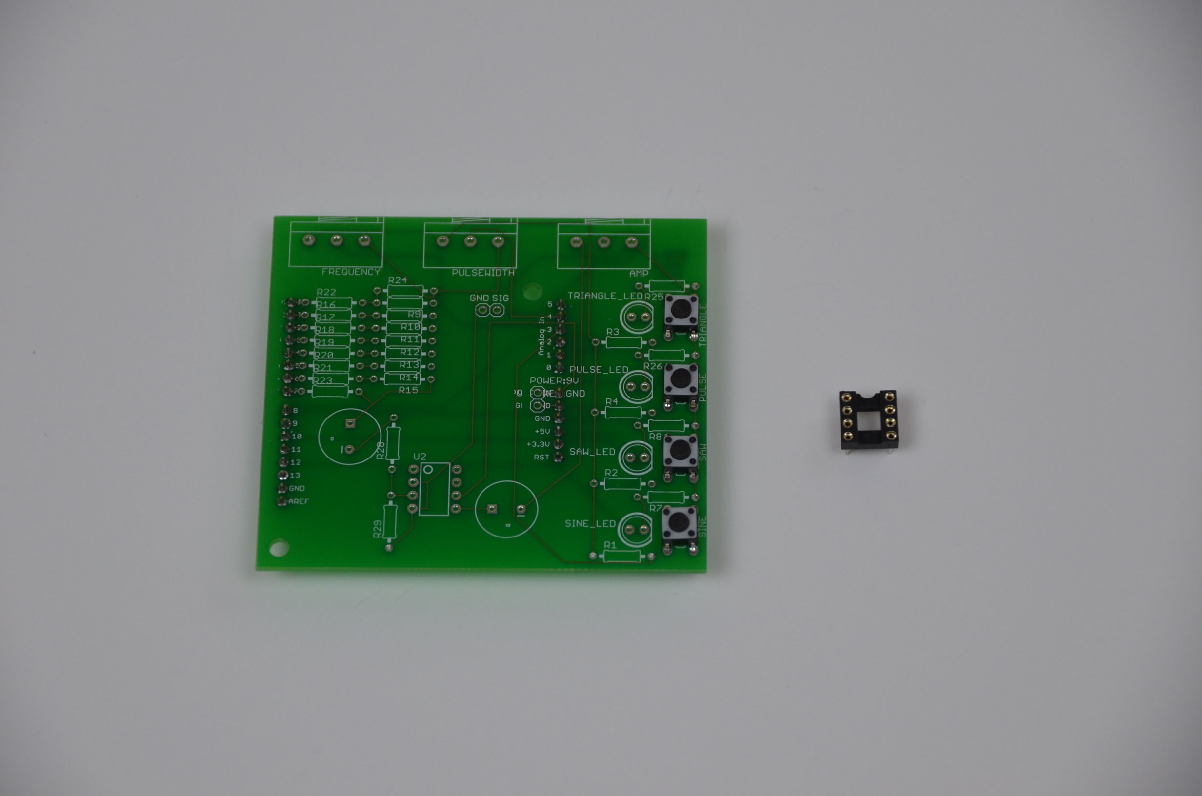
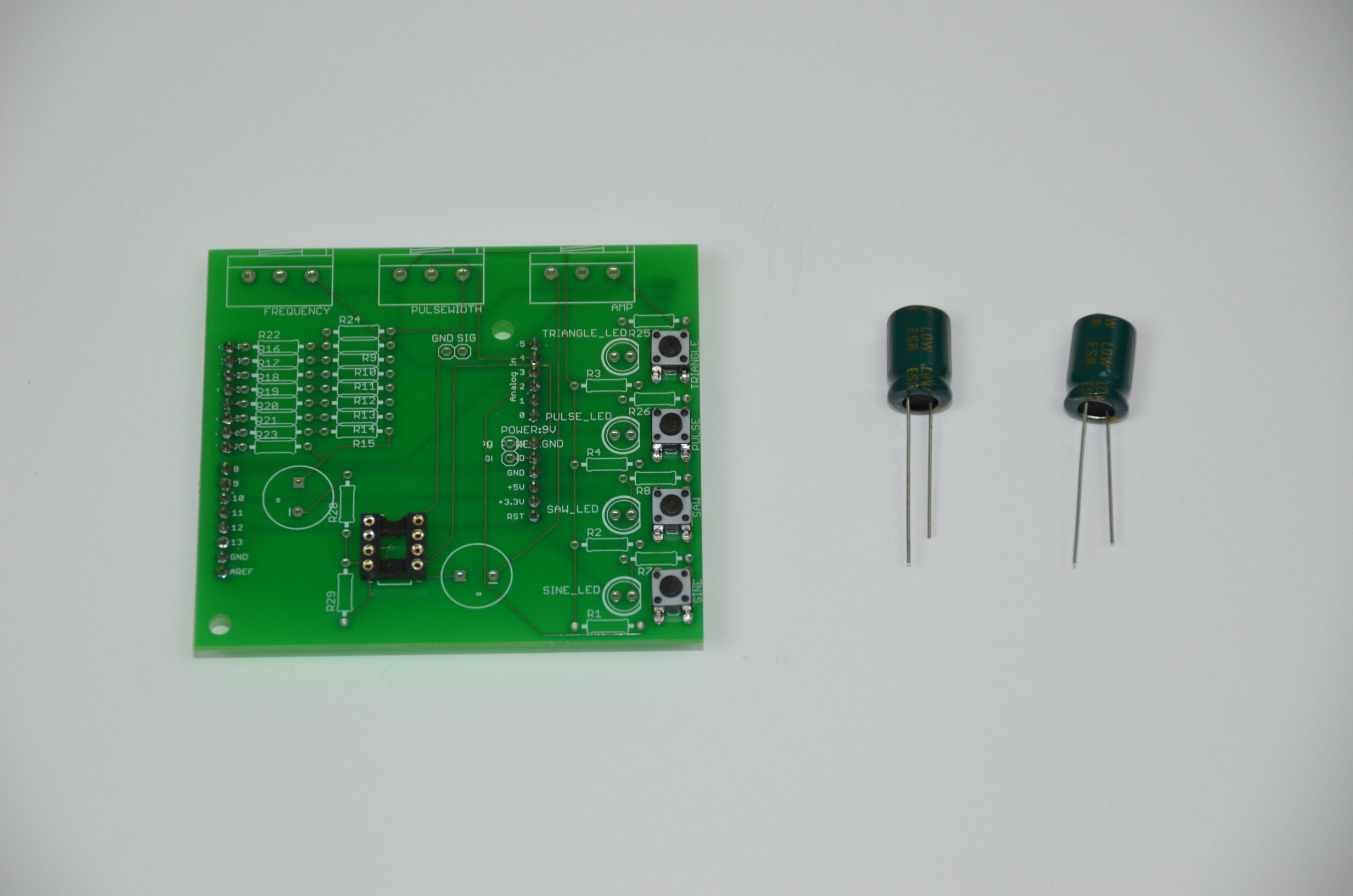
The 8 pin IC socket for the LM386 audio amplifier is soldered into the PCB next, along with two 220uF capacitors. Take special note, the capacitors have a minus (-) sign marking that denotes which side is the negative wire. The PCB also has a minus (-) sign on the white silkscreen. Make sure you match these two up while connecting and soldering the capacitors to the board.

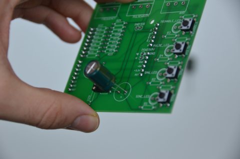
Below you can see a close-up of the white silk-screen minus (-) sign and me slowly inserting the capcitor into the PCB for soldering. It's important to put the capacitors in the correct way or things won't work properly!
The first half of the PCB assembly is the easy part. The next half is all about soldering in the many resistors that we have, to create the resistor ladder that we saw in the theory section.
The PCB, for the Arduino Waveform Generator kit can be seen in the pictures below, means you need only solder the right parts into the right locations. With the white silkscreen, it is obvious where each part goes making assembly a breeze.

The 8x8x8 LED Cube kit required you to figure out the layout and wiring of the circuit board using a protoboard which was a headache and a lot of extra effort. But as you can see, the PCB has that taken care of already, so let's get to soldering!
To start things off, we'll cut the header pins so that they fit into the Arduino specific holes. Solder the outer two pins of the header first so that you can get each header placed properly and evenly.
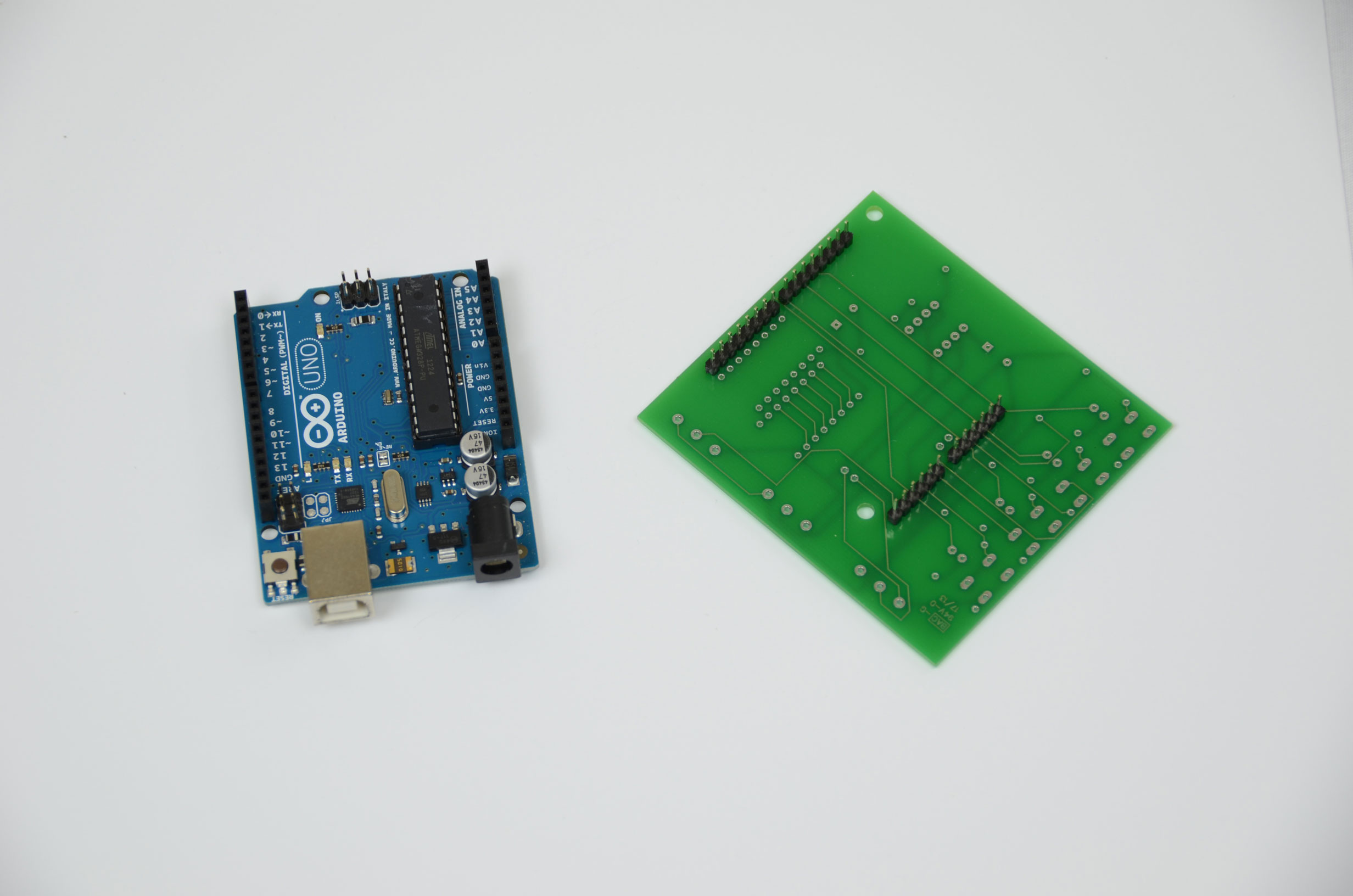
Once the header pins are all soldered into place, the PCB should fit into an Arduino UNO with no effort. You can see an example image below of how the PCB connects to an Arduino. However, we're not even close to finished. Next we'll solder on the 4 tactile push buttons.

The 8 pin IC socket for the LM386 audio amplifier is soldered into the PCB next, along with two 220uF capacitors. Take special note, the capacitors have a minus (-) sign marking that denotes which side is the negative wire. The PCB also has a minus (-) sign on the white silkscreen. Make sure you match these two up while connecting and soldering the capacitors to the board.
Below you can see a close-up of the white silk-screen minus (-) sign and me slowly inserting the capcitor into the PCB for soldering. It's important to put the capacitors in the correct way or things won't work properly!

The first half of the PCB assembly is the easy part. The next half is all about soldering in the many resistors that we have, to create the resistor ladder that we saw in the theory section.