The Schematic
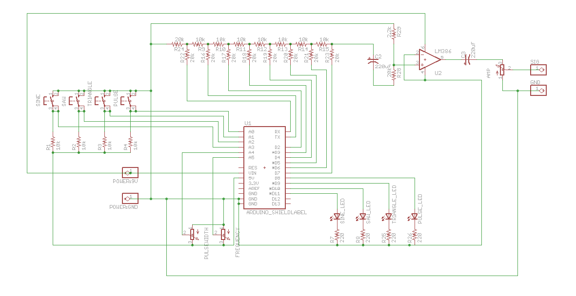
The schematic for this project has 5 main sections: the input buttons, the output LEDs, the Arduino shield, the resistor ladder and the operational amplifier output. Click on the schematic image below to get a bigger view of it.

Below we'll take a further look into the theory of how this waveform generator work but looking at two unqiue electrical ideas, resistors ladders and DDS systems.
Resistor Ladder
The key to producing different analog voltages with the Arduino comes from the resistor ladder. A resistor ladder can be anywhere from 1 to X bits large, which means that a certain X number of bits will control the output Voltage of the resistor ladder. In our case, we will be using an 8-bit resistor ladder, which means 8 I/O pins from the Arduino will control the voltage output from the resistor ladder giving a total of 256 unique voltages that can be output from +0v to +9v.
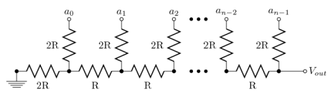
The picture above shows you wikipedia's interpretation of a Resistor Ladder with all the theory and math described out in full detail. If you're into the theory side you can plug in the values of the resistors from our schematic above and theoretically verify that the output voltages are the same as what comes out of the final kit.
Simple DDS Theory
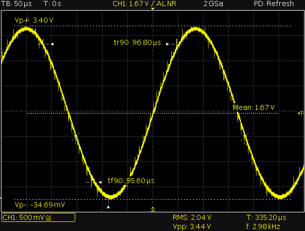
A DDS or Direct Digital Synthesizer is a type of electrical device that converts digital data directly into arbitrary waveforms using a single reference clock frequency. The reference frequency in simple DDS systems defines how fast and how accurate the synthesized waveforms can be. For example if you loook at the sine wave below you see it looks rather continuous.
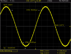
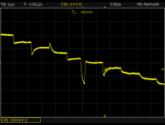
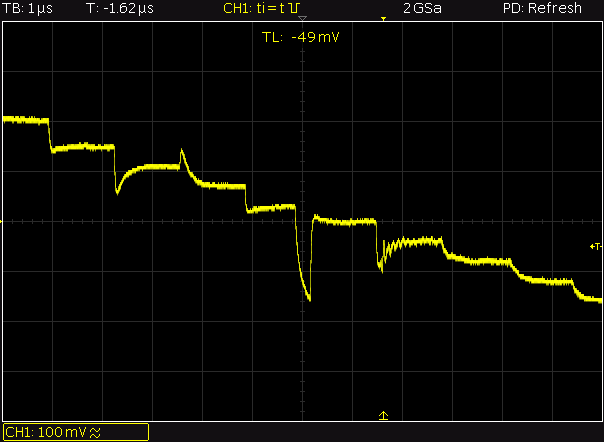
However, upon closer inspection you can actually see each individual step occuring one after another like a stairway. This is typically acceptable and can be smoothed out with filters and additional analog circuitry, however it does limit how fast and accurate your waveforms can be.
The schematic for this project has 5 main sections: the input buttons, the output LEDs, the Arduino shield, the resistor ladder and the operational amplifier output. Click on the schematic image below to get a bigger view of it.
Below we'll take a further look into the theory of how this waveform generator work but looking at two unqiue electrical ideas, resistors ladders and DDS systems.
Resistor Ladder
The key to producing different analog voltages with the Arduino comes from the resistor ladder. A resistor ladder can be anywhere from 1 to X bits large, which means that a certain X number of bits will control the output Voltage of the resistor ladder. In our case, we will be using an 8-bit resistor ladder, which means 8 I/O pins from the Arduino will control the voltage output from the resistor ladder giving a total of 256 unique voltages that can be output from +0v to +9v.

The picture above shows you wikipedia's interpretation of a Resistor Ladder with all the theory and math described out in full detail. If you're into the theory side you can plug in the values of the resistors from our schematic above and theoretically verify that the output voltages are the same as what comes out of the final kit.
Simple DDS Theory
A DDS or Direct Digital Synthesizer is a type of electrical device that converts digital data directly into arbitrary waveforms using a single reference clock frequency. The reference frequency in simple DDS systems defines how fast and how accurate the synthesized waveforms can be. For example if you loook at the sine wave below you see it looks rather continuous.
However, upon closer inspection you can actually see each individual step occuring one after another like a stairway. This is typically acceptable and can be smoothed out with filters and additional analog circuitry, however it does limit how fast and accurate your waveforms can be.