Hardware Design
Before going into how VHDL works, I want to make sure you already have the DIP Switch installed on the Dev Board. If you followed the Verilog tutorial and have done this already, skip this section. Otherwise: we'll install the additional hardware onto the CPLD Development Board. This shouldn't take very long, it's a matter of connecting a few devices with wirewrap and getting the new additions situated on the board.
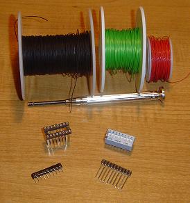
These are the parts & tools that will be used for the addition to the CPLD Development Board:
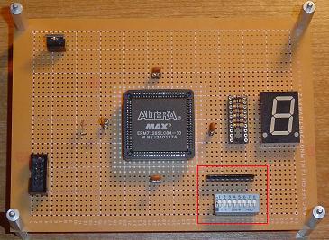
Here is where the Resistor Array & Dip Switch should be placed on the board (although you can put it wherever you want, this is just how I did it):
The wiring shouldn't take very long. The resistor array has spots for 10 wires, however for this tutorial only 8 will be used as the DIP switch only has 8 switches:
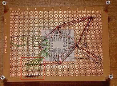
The wires are connected from the resistor array to the CPLD I/O pins. In this tutorial, PINS 53-61 are used, feel free to use any open pins you like, these were just clostest and most convenient.
Before going into how VHDL works, I want to make sure you already have the DIP Switch installed on the Dev Board. If you followed the Verilog tutorial and have done this already, skip this section. Otherwise: we'll install the additional hardware onto the CPLD Development Board. This shouldn't take very long, it's a matter of connecting a few devices with wirewrap and getting the new additions situated on the board.
These are the parts & tools that will be used for the addition to the CPLD Development Board:
Here is where the Resistor Array & Dip Switch should be placed on the board (although you can put it wherever you want, this is just how I did it):
The wiring shouldn't take very long. The resistor array has spots for 10 wires, however for this tutorial only 8 will be used as the DIP switch only has 8 switches:
The wires are connected from the resistor array to the CPLD I/O pins. In this tutorial, PINS 53-61 are used, feel free to use any open pins you like, these were just clostest and most convenient.