Hardware Design
Before going into how Verilog works, we'll install the additional hardware onto the CPLD Development Board. This shouldn't take very long, it's a matter of connecting a few devices with wirewrap and getting the new additions situated on the board.
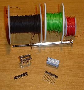
These are the parts & tools that will be used for the addition to the CPLD Development Board:
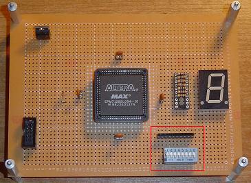
Here is where the Resistor Array & Dip Switch should be placed on the board (although you can put it wherever you want, this is just how I did it):
The wiring shouldn't take very long. The resistor array has spots for 10 wires, however for this tutorial only 8 will be used as the DIP switch only has 8 switches:
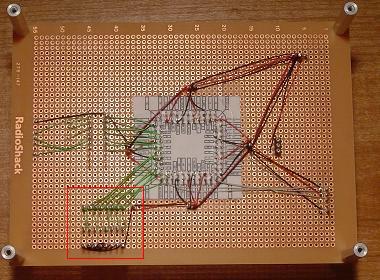
The wires are connected from the resistor array to the CPLD I/O pins. In this tutorial, PINS 53-61 are used, feel free to use any open pins you like, these were just clostest and most convenient.
Before going into how Verilog works, we'll install the additional hardware onto the CPLD Development Board. This shouldn't take very long, it's a matter of connecting a few devices with wirewrap and getting the new additions situated on the board.
These are the parts & tools that will be used for the addition to the CPLD Development Board:
Here is where the Resistor Array & Dip Switch should be placed on the board (although you can put it wherever you want, this is just how I did it):
The wiring shouldn't take very long. The resistor array has spots for 10 wires, however for this tutorial only 8 will be used as the DIP switch only has 8 switches:
The wires are connected from the resistor array to the CPLD I/O pins. In this tutorial, PINS 53-61 are used, feel free to use any open pins you like, these were just clostest and most convenient.