Schematic Overview
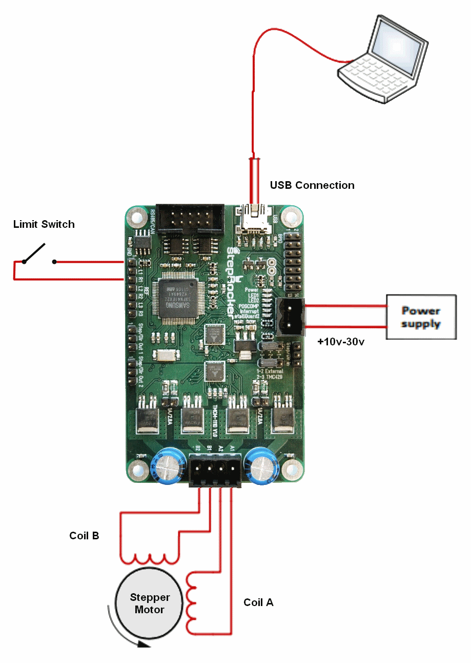
The schematic below shows you how we connected the motor and mechanics to the TMCM-1110 stepRocker board. The power supply connection can also be seen.

View Full Schematic
Schematic Specifics
Power Supply
The power supply for the stepRocker is a +10v-30v input. I didn't have a proper power supply to use with this system, so I'll just be using two battery backs connected together to get about +14v for a power supply.
Limit Switch Connections
The limit switch is nothing more than a pushbutton switch and it connects R1 to ground when it is pressed. Any other time, the limit switch should be open-circuit.
Stepper Motor Connections
This stepper motor controller can only control bi-polar stepper motors so make sure your motor has 2 coils. Double check the datasheet to see which color wire from the stepper motor connects to what part of each coil.
The schematic below shows you how we connected the motor and mechanics to the TMCM-1110 stepRocker board. The power supply connection can also be seen.
View Full Schematic
Schematic Specifics
Power Supply
The power supply for the stepRocker is a +10v-30v input. I didn't have a proper power supply to use with this system, so I'll just be using two battery backs connected together to get about +14v for a power supply.
Limit Switch Connections
The limit switch is nothing more than a pushbutton switch and it connects R1 to ground when it is pressed. Any other time, the limit switch should be open-circuit.
Stepper Motor Connections
This stepper motor controller can only control bi-polar stepper motors so make sure your motor has 2 coils. Double check the datasheet to see which color wire from the stepper motor connects to what part of each coil.