Hardware Design
So we saw the schematic and some theory about how SPI works, let's build something that actually works and uses SPI!
Building The Circuit
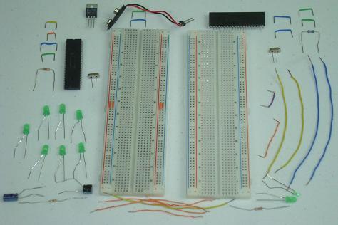
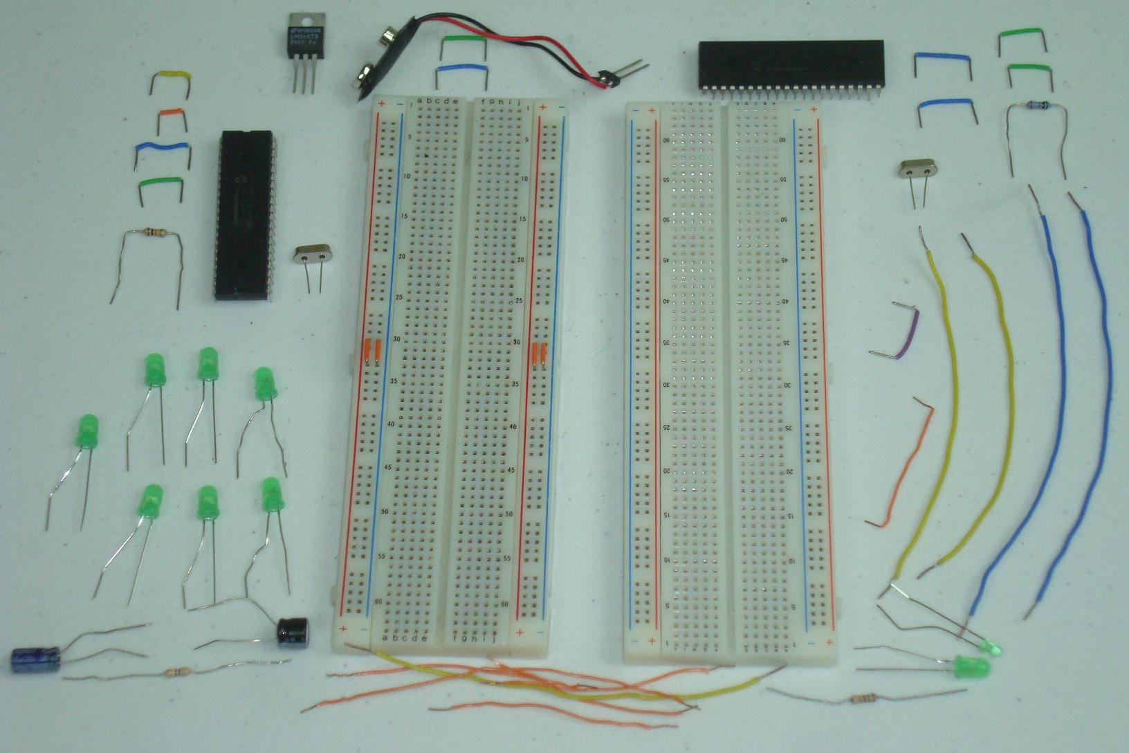
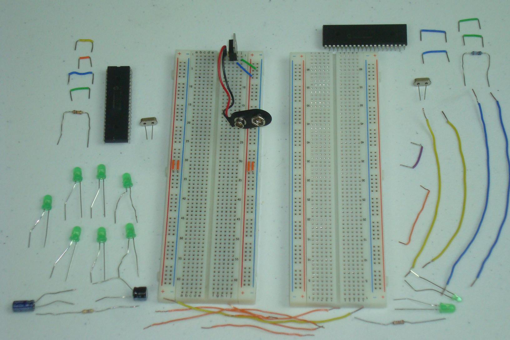
Get all the parts together from the parts list and the schematic. You can see a picture of all the parts used below.
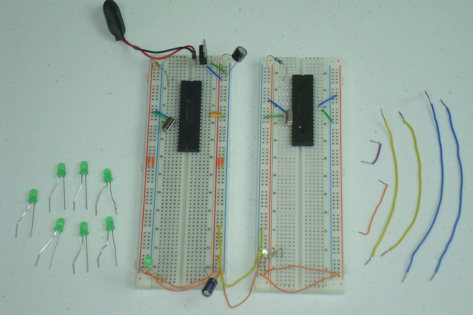
·First the 7805 +5v regulator circuit is built.

·Power and Ground connections are made, along with power LEDs.
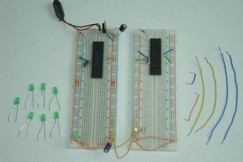
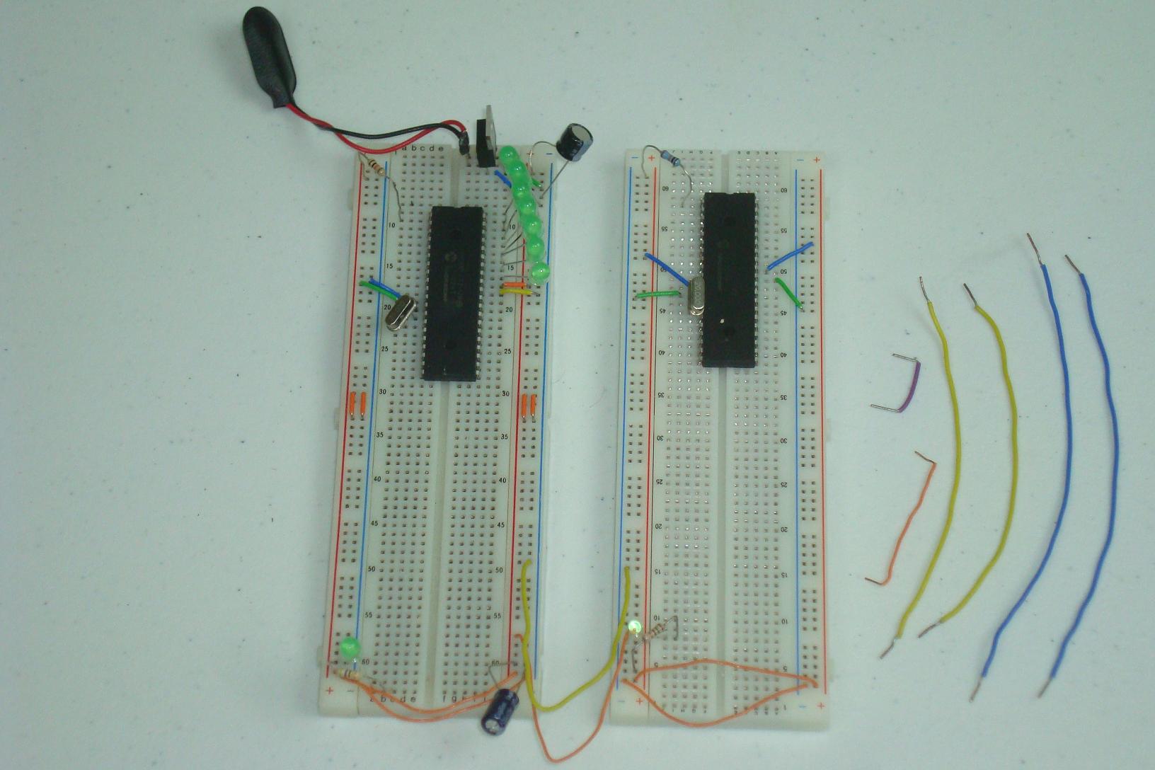
·The 7 LEDs are connected to PORTB RB6-RB0 of the PIC.

·The 4 SPI control lines connect the two PICs together. The SPI master and slave connections are now in place.
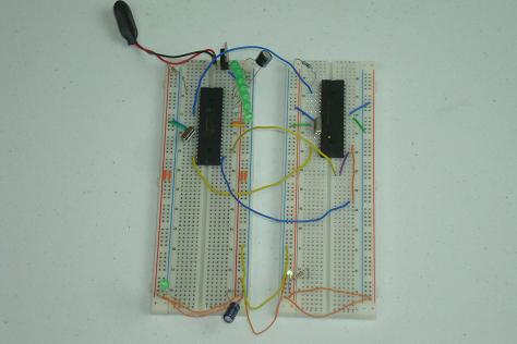
·That's it! 2 PICs, some wires and some LEDs. Now let's check out how the firmware was written.
So we saw the schematic and some theory about how SPI works, let's build something that actually works and uses SPI!
Building The Circuit
Get all the parts together from the parts list and the schematic. You can see a picture of all the parts used below.
·First the 7805 +5v regulator circuit is built.
·Power and Ground connections are made, along with power LEDs.
·The 7 LEDs are connected to PORTB RB6-RB0 of the PIC.
·The 4 SPI control lines connect the two PICs together. The SPI master and slave connections are now in place.
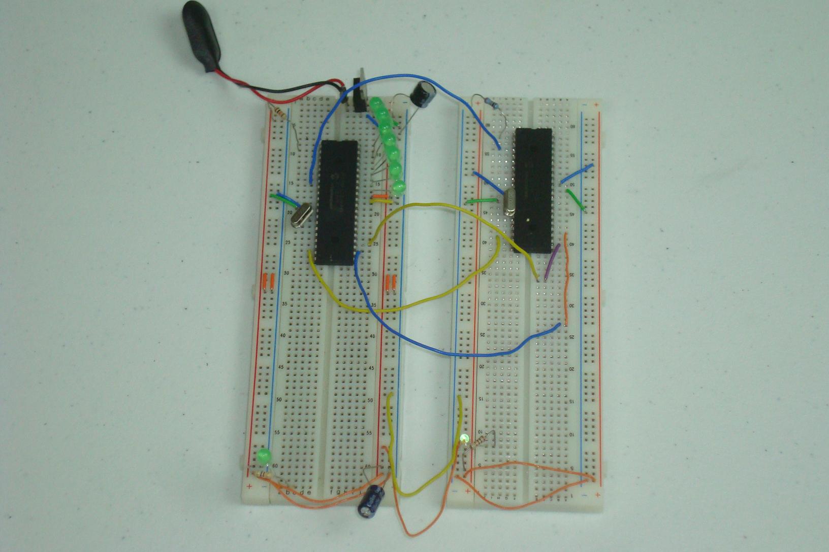
·That's it! 2 PICs, some wires and some LEDs. Now let's check out how the firmware was written.