PS/2 Communication Theory
This section will go through the theory of the specific connectors we will be using and their associated pinouts, as well as an example data output from a PS/2 keyboard device. PS/2 is a serial protocol and only uses 2 pins to communication information. The data pin is actually bi-directional, but we will only consider the data-output from the PS/2 device.
PS/2 Connectors


The standard pinout for a mini-din or PS/2 port can be seen above for both the male and female connectors. Typically the male connector is on the keyboard/mouse or whatever PS/2 device you have and the female connector will be on the receiving device (laptop/desktop) which is the PIC 18F452 in our case.
PS/2 Data Output
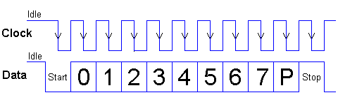
The timing diagram seen above is the standard way for any PS/2 device to output data. It follows a specific sequence everytime:
The main points to catch from the timing diagram is that: [1] for every 8 bits of data output, there is a start and a stop bit and [2] all data output is valid only on a falling clock edge.
This section will go through the theory of the specific connectors we will be using and their associated pinouts, as well as an example data output from a PS/2 keyboard device. PS/2 is a serial protocol and only uses 2 pins to communication information. The data pin is actually bi-directional, but we will only consider the data-output from the PS/2 device.
6-pin Mini-DIN (PS/2):
1 - Data
2 - Not Implemented
3 - Ground
4 - Vcc (+5V)
5 - Clock
6 - Not Implemented
1 - Data
2 - Not Implemented
3 - Ground
4 - Vcc (+5V)
5 - Clock
6 - Not Implemented
The standard pinout for a mini-din or PS/2 port can be seen above for both the male and female connectors. Typically the male connector is on the keyboard/mouse or whatever PS/2 device you have and the female connector will be on the receiving device (laptop/desktop) which is the PIC 18F452 in our case.
The timing diagram seen above is the standard way for any PS/2 device to output data. It follows a specific sequence everytime:
- [1] Data Bit Goes Low
- [2] Clock Goes Low
- [3] Data Kept Low (Start Bit)
- [4] Clock Goes High
- [5] 8 Data Bits Clocked Out
- [6] Parity Data Bit Kept High
- [7] 1 Clock Cycle
- [8] Stop Data Bit Kept High
- [9] 1 Clock Cycle
The main points to catch from the timing diagram is that: [1] for every 8 bits of data output, there is a start and a stop bit and [2] all data output is valid only on a falling clock edge.