Schematic Overview
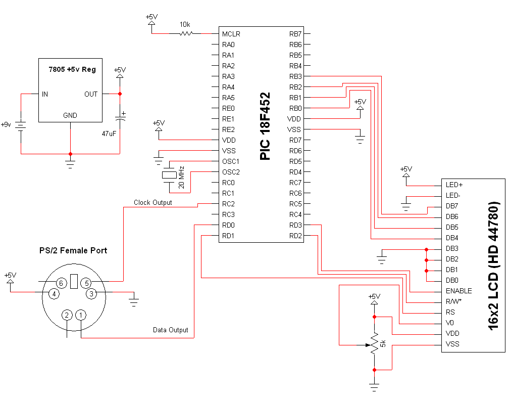
The schematic for this tutorial was kept as simple as possible so we could keep focus on what interrupts are and how we use them on the PIC. You can see the completed schematic for this project below. The main parts in the schematic are the 16x2 LCD, 18F452 and PS/2 Port.
View Full Schematic
Schematic Specifics
Power Regulator
If you follow my projects and tutorials you'll recognize this circuit. It's an extremely simple and straight forward +5v regulator circuit with bypass capacitor.
PS/2 Connector
Be sure to look up the pinout for the PS/2 connector that you end up using, some might have different pinouts. Pins 2 and 6 are reserved for future use and are not used to communicate with the keyboard so they aren't wired up. Pins 4 and 3 are +5v and ground. Pins 1 and 5 are the Serial Data output and Clock output.
16x2 LCD Display
The display control bits Register Select, Read/Write* and Enable connect to PortD - RD1, RD2 and RD3. The data bits DB4, DB5, DB6 and DB7 connect to PORTB - RB0, RB1, RB2 and RB3. The rest of the data bits are connected to ground. This means that the LCD must use the 4 data bit mode, which saves us electrical connections but adds a little more software overhead.