Hardware Design
Looking at the theory and proposed schematic is fun, but we need to actually build this thing and see it in action. Below are the steps that it takes to build the circuit on a breadboard.
Building The Circuit
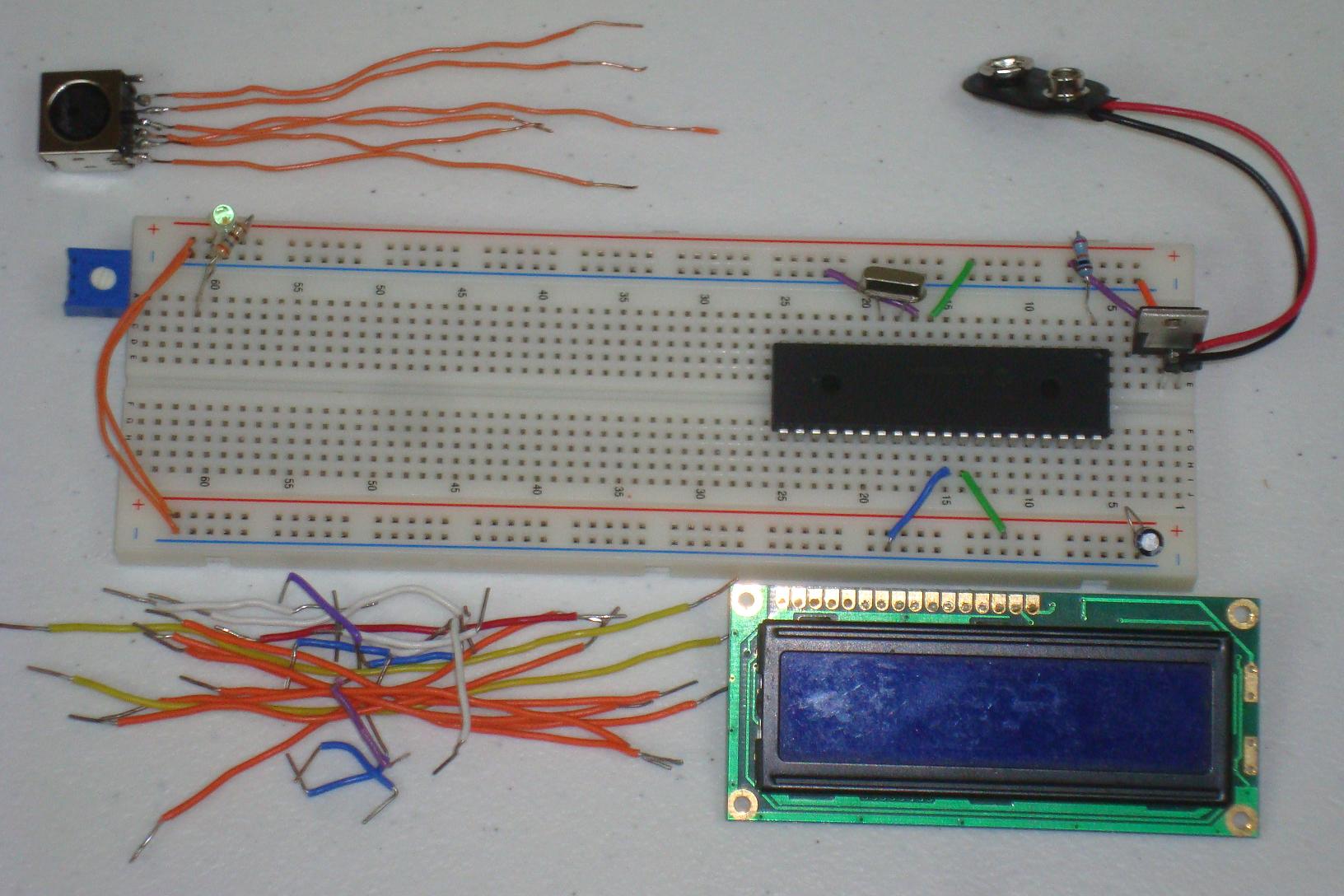
Get your parts together and follow the schematic. I built mine and in stages as you can see below...
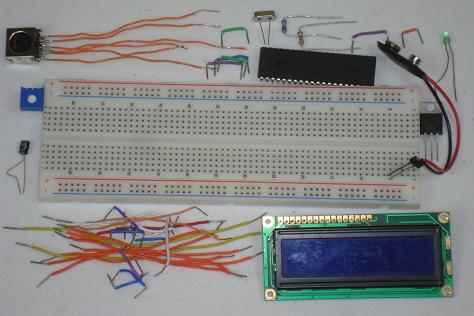
·First the power regulator circuit is connected on the breadboard.
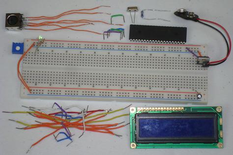
·The PIC microcontroller circuit comes next.

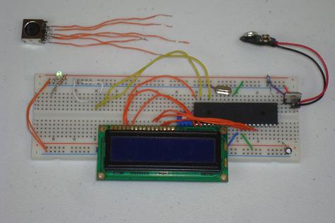
·The LCD is connected next. Since we're using the 4-bit data mode, make sure to connect the lower 4 data bits DB0 - DB3 to ground.

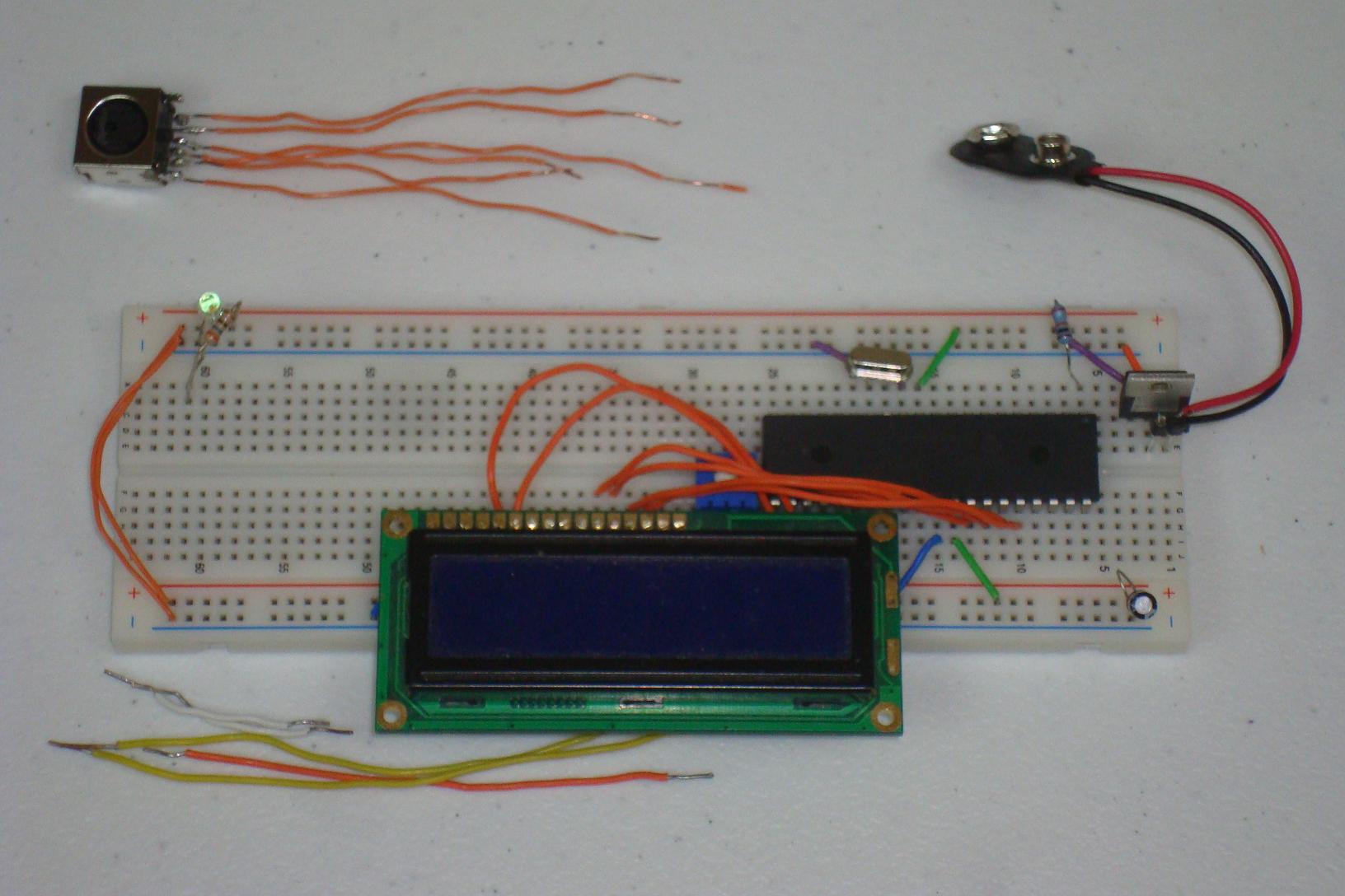
·Next, 4 wires carry power, ground, data and clk to the PS/2 female connector.
·The PS/2 female connector is connected to the breadboard with some lead wires I soldered to it.
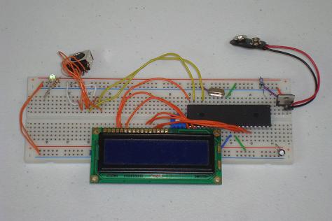
·Presto, Finished! Just follow the schematic if you're in doubt. One last note: double check if your LCD's backlight requires a current limiting resistor, or if you can connect the backlight directly to power and ground like I did.
Looking at the theory and proposed schematic is fun, but we need to actually build this thing and see it in action. Below are the steps that it takes to build the circuit on a breadboard.
Building The Circuit
Get your parts together and follow the schematic. I built mine and in stages as you can see below...

·First the power regulator circuit is connected on the breadboard.

·The PIC microcontroller circuit comes next.
·The LCD is connected next. Since we're using the 4-bit data mode, make sure to connect the lower 4 data bits DB0 - DB3 to ground.
·Next, 4 wires carry power, ground, data and clk to the PS/2 female connector.

·The PS/2 female connector is connected to the breadboard with some lead wires I soldered to it.

·Presto, Finished! Just follow the schematic if you're in doubt. One last note: double check if your LCD's backlight requires a current limiting resistor, or if you can connect the backlight directly to power and ground like I did.