Project Info
Author: Chris
Difficulty: Easy-Medium
Time Invested: 2 Hours
Prerequisites:
Take a look at the above
articles before continuing
to read this article.
Author: Chris
Difficulty: Easy-Medium
Time Invested: 2 Hours
Prerequisites:
Take a look at the above
articles before continuing
to read this article.
In this article, we will go step-by-step through the process of understanding, designing and building a system that uses an infrared proximity sensor for input, correlates that input to how far away an object is from the sensor and then drives a motor and some LEDs at distinct speeds depending upon the proximity of the object.
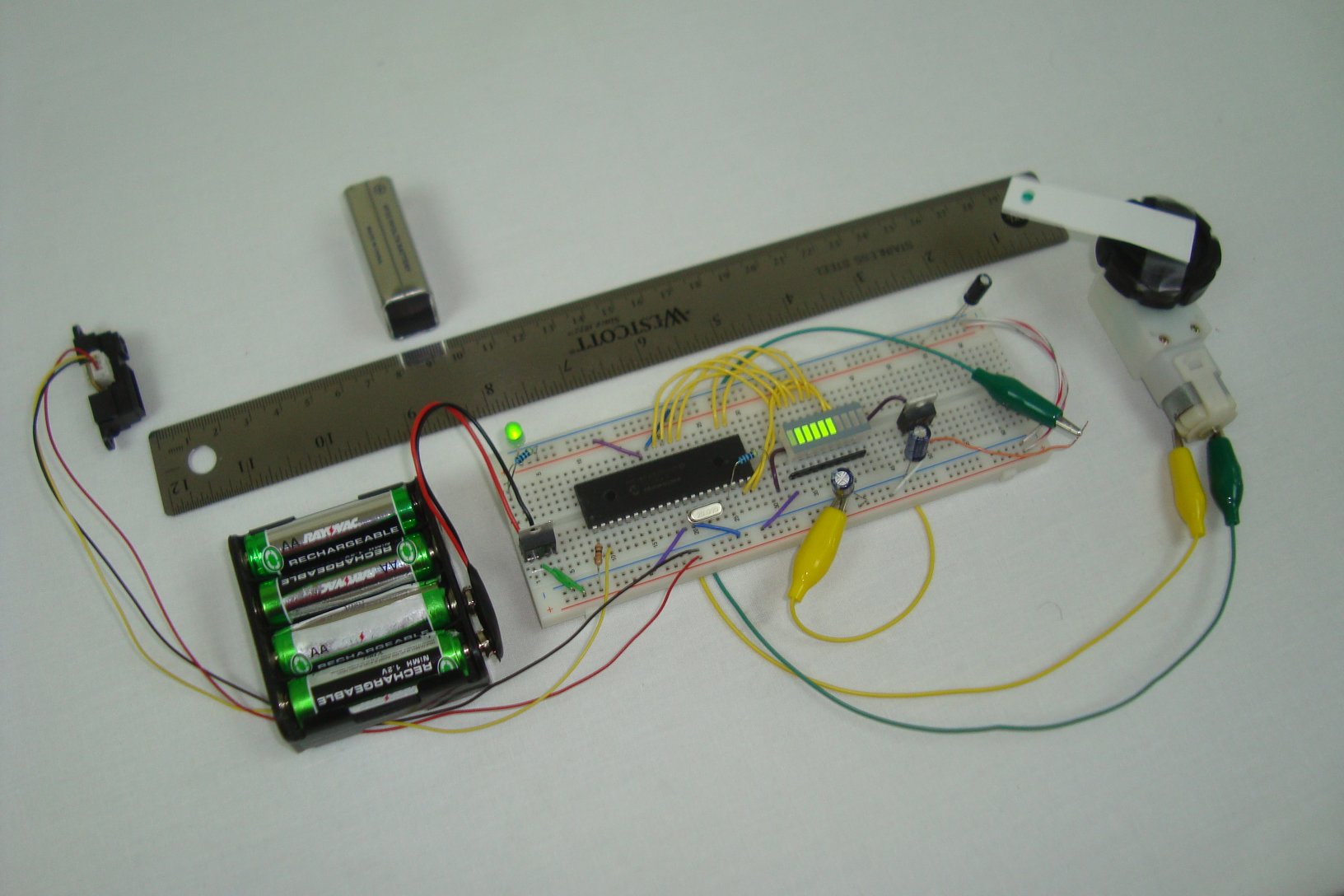
Purpose & Overview Of This Project
The goal of this project and article is to explain how to use an infrared proximity sensor to drive a motor. The system should be able to drive the motor at 8 different speeds (1 = slowest, 8 = fastest), likewise a representative LED bar will be added to give a second visual speed indicator. Up to 8 LEDs will be controlled to represent the 8 different levels of speed.
To make this system we will use a sharp ir distance sensor (10cm-80cm) for detecting how far away the object is, a PIC 18F4520 microcontroller to interpret the input and drive the output, a 10 LED Bar for giving a visual indication of what speed we're at, and a TIP42 + DC motor for the actual motor and power transistor to drive the motor.