Schematic Overview
The schematic for this project has 4 main parts, the 18F4520 microcontroller, the sharp IR distance sensor, the power transistor and the LED bar. You can see how these parts are connected together to build the system we want in the schematic below:
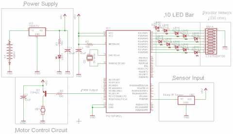
View Full Schematic
Schematic Specifics
Power Supply
To make things simple, we'll use a 7805 +5v regulator to supply the power for this entire project.
IR Distance Sensor Input
The IR Proximity Sensor has a 3 pin connector that is super simple, Vsupply, Gnd, Vout. Vsupply is connected to +5v power and Gnd to Ground. Vout will be connecting to pin RA0 of the microcontroller, this is an analog-to-digital converter pin.
Motor Control Circuit
The TIP42 power transistor allows the motor to be turn off or on. The base pin of the TIP42 is connected to the PIC microcontroller's CCP1 pin, which is a PWM output pin from the PIC. PWM will be used to drive the motor at different speeds as we discussed in the theory section.
LED Bar Output
To give a visual read-out of the current status and speed level (level 0 to 8, 0 motor is off, 8 motor is full speed!) we'll use an LED Bar connected to the PIC microcontroller's PORTD. This port has 8 digital I/O pins which will each drive a single LED, on the LED Bar.
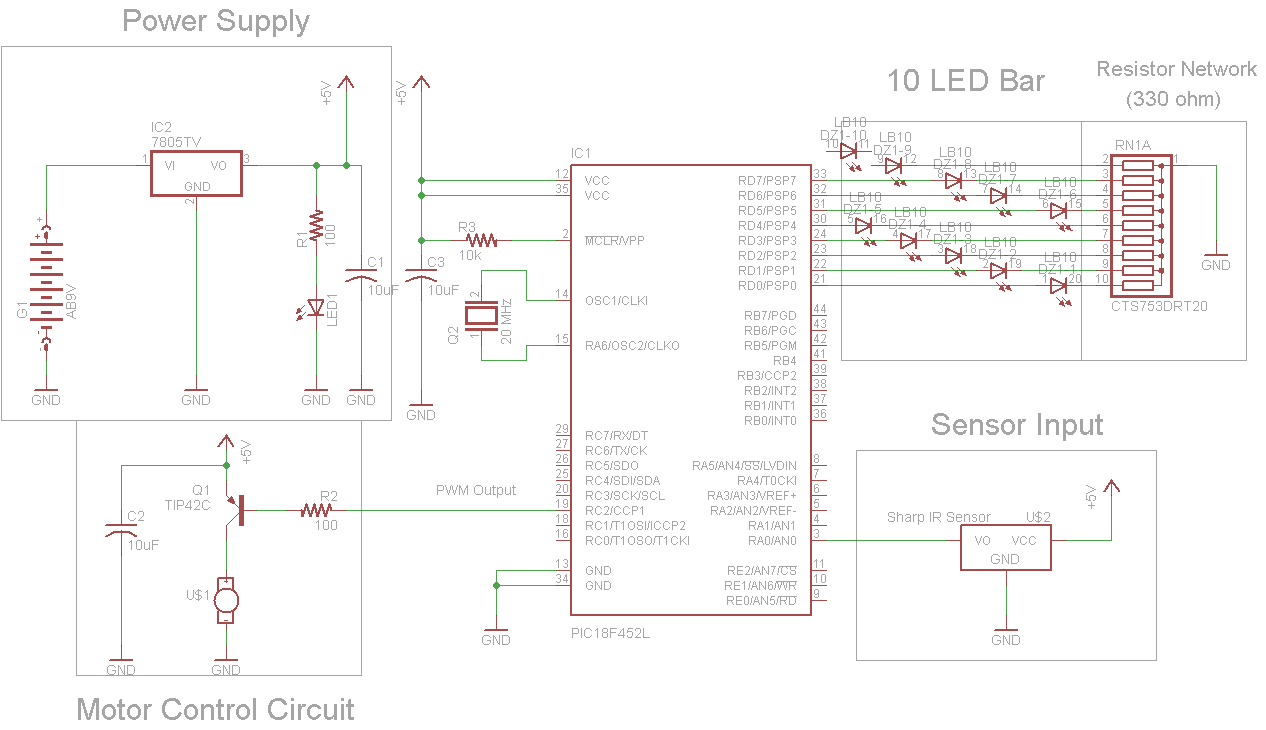
The schematic for this project has 4 main parts, the 18F4520 microcontroller, the sharp IR distance sensor, the power transistor and the LED bar. You can see how these parts are connected together to build the system we want in the schematic below:
View Full Schematic
Schematic Specifics
Power Supply
To make things simple, we'll use a 7805 +5v regulator to supply the power for this entire project.
IR Distance Sensor Input
The IR Proximity Sensor has a 3 pin connector that is super simple, Vsupply, Gnd, Vout. Vsupply is connected to +5v power and Gnd to Ground. Vout will be connecting to pin RA0 of the microcontroller, this is an analog-to-digital converter pin.
Motor Control Circuit
The TIP42 power transistor allows the motor to be turn off or on. The base pin of the TIP42 is connected to the PIC microcontroller's CCP1 pin, which is a PWM output pin from the PIC. PWM will be used to drive the motor at different speeds as we discussed in the theory section.
LED Bar Output
To give a visual read-out of the current status and speed level (level 0 to 8, 0 motor is off, 8 motor is full speed!) we'll use an LED Bar connected to the PIC microcontroller's PORTD. This port has 8 digital I/O pins which will each drive a single LED, on the LED Bar.