Hardware Design
Lucky for us the hardware design and construction process is only 5 steps. Scroll down to see how it starts out!
Putting Everything Together
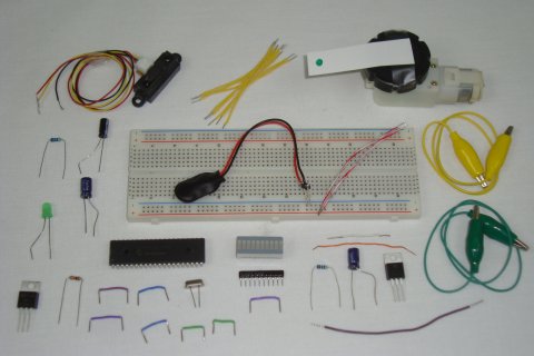
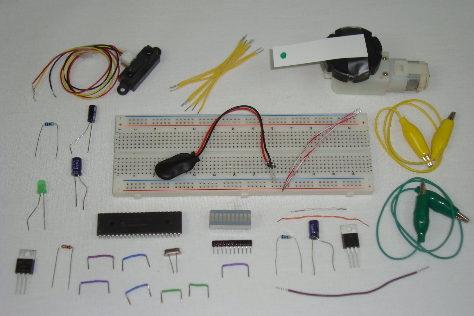
Double check you have all the parts seen in the schematic and get ready to start building! The first step is always gathering the parts together so you can start building. Below you can see all the parts. I chose to use some alligator clips to connect the motor to the circuit instead of plain wire.
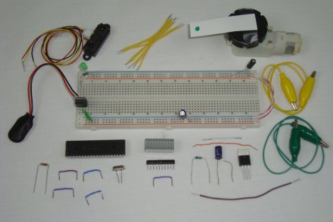
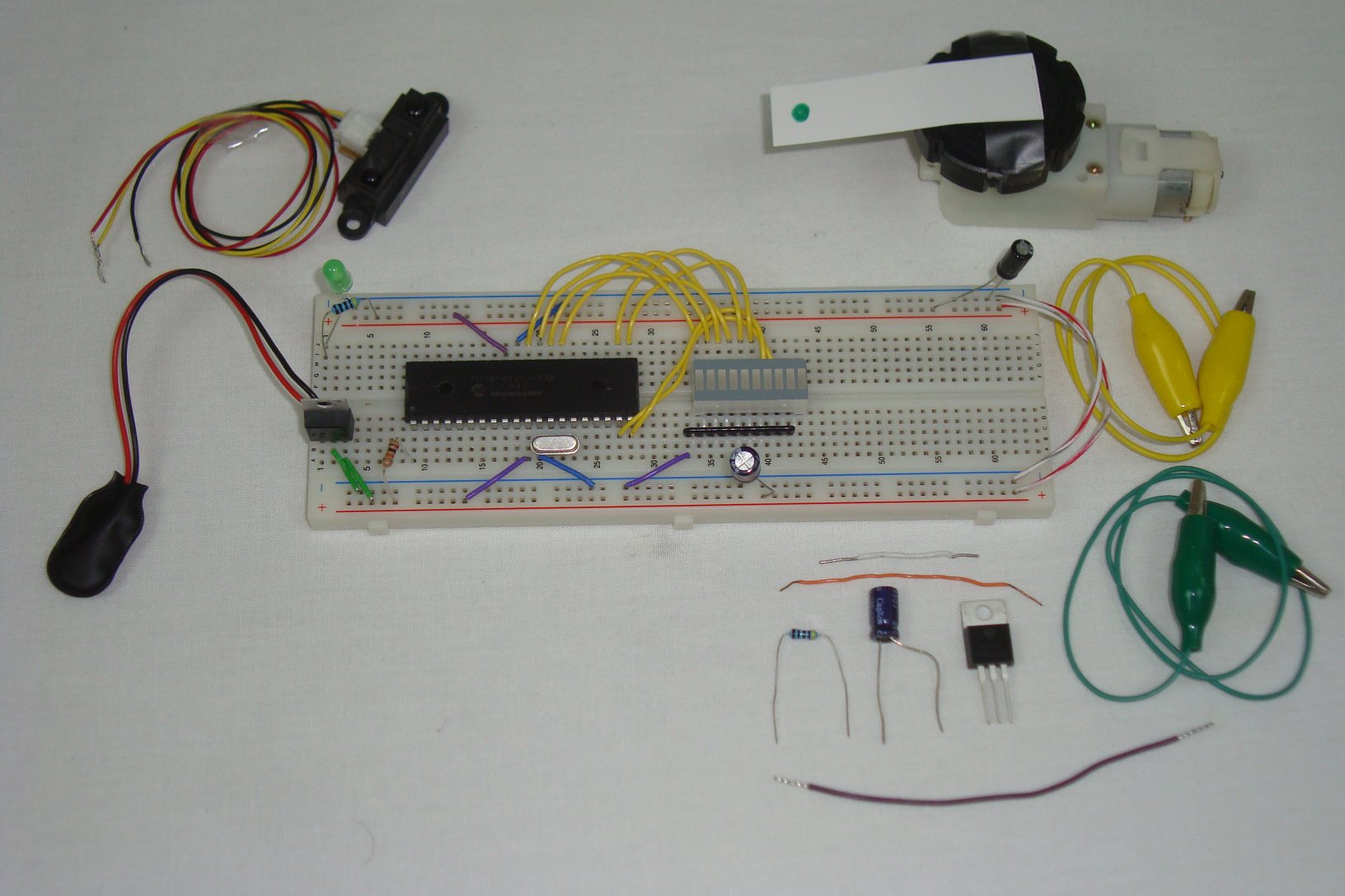
The first connections are all the power supply connections, capacitors and power LED.
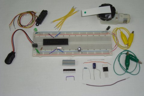
Next, the basic PIC circuit is added to the breadboard, with power, ground, crystal and 10kΩ connected to the PIC.
Now, the LED Bar and resistor network are connected to the PIC's PORTD.
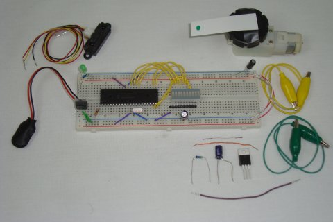
For the final step, connect the motor control circuit and IR distance sensor to the PIC.

That's it! Now let's take a look at the PIC's firmware/software to see how we'll capture input and turn it into nifty motor controlling output!
Lucky for us the hardware design and construction process is only 5 steps. Scroll down to see how it starts out!
Putting Everything Together
Double check you have all the parts seen in the schematic and get ready to start building! The first step is always gathering the parts together so you can start building. Below you can see all the parts. I chose to use some alligator clips to connect the motor to the circuit instead of plain wire.
The first connections are all the power supply connections, capacitors and power LED.

Next, the basic PIC circuit is added to the breadboard, with power, ground, crystal and 10kΩ connected to the PIC.

Now, the LED Bar and resistor network are connected to the PIC's PORTD.
For the final step, connect the motor control circuit and IR distance sensor to the PIC.
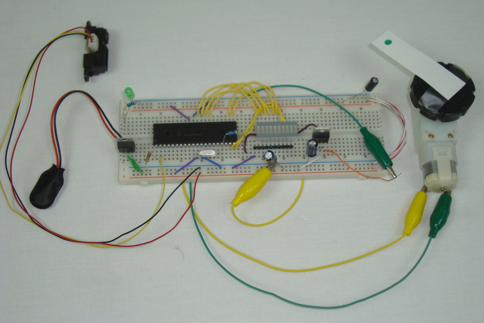
That's it! Now let's take a look at the PIC's firmware/software to see how we'll capture input and turn it into nifty motor controlling output!