Schematic Overview
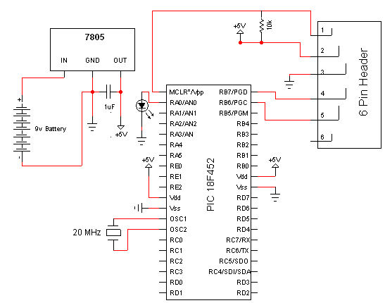
The schematic for this project is the basic PIC programming circuit. Many safety components that a professional designer would add to the circuit have been deleted to make the circuit as simple as possible. Since we're doing simple hobby electronics this doesn't really make a difference. The main parts in the schematic are the PICKit3, PIC 18F452 and 7805.
PIC ICSP Programming Schematic

View Full Schematic
Schematic Specifics
Power Regulator
The 7805 converts the input +9v down to a +5v output which powers the PIC. The PIC has two spots where it connects to power and ground, and there is a single 10kΩ resistor connected to the MCLR Pin1 of the pic that goes to power.
ICSP connection
ICSP is short for in-circuit serial programmer and this is the port used on almost every PIC microcontroller to load your program onto it. The PICKit3 has the same pinout as the connector seen above, the little dot on the PICKit3 tells you which connection is PIN1 or MCLR.
LED Output
A single led can be seen off of PORTA RA1 or PIN2 on the PIC. This led will be used to confirm that out program was successfully loaded onto the PIC by flashing on and off at a predetermined speed.
The schematic for this project is the basic PIC programming circuit. Many safety components that a professional designer would add to the circuit have been deleted to make the circuit as simple as possible. Since we're doing simple hobby electronics this doesn't really make a difference. The main parts in the schematic are the PICKit3, PIC 18F452 and 7805.
PIC ICSP Programming Schematic
View Full Schematic
Schematic Specifics
Power Regulator
The 7805 converts the input +9v down to a +5v output which powers the PIC. The PIC has two spots where it connects to power and ground, and there is a single 10kΩ resistor connected to the MCLR Pin1 of the pic that goes to power.
ICSP connection
ICSP is short for in-circuit serial programmer and this is the port used on almost every PIC microcontroller to load your program onto it. The PICKit3 has the same pinout as the connector seen above, the little dot on the PICKit3 tells you which connection is PIN1 or MCLR.
LED Output
A single led can be seen off of PORTA RA1 or PIN2 on the PIC. This led will be used to confirm that out program was successfully loaded onto the PIC by flashing on and off at a predetermined speed.