Hardware Design
In this hardware section we will assemble the circuit seen in the schematic step by step so that you can easily follow along and assemble the circuit yourself. Please note that I added a single resistor and LED to power and ground so that I can tell when the power is successfully connected. This small power LED circuit isn't shown in the schematic.
Building The Circuit
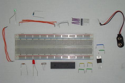
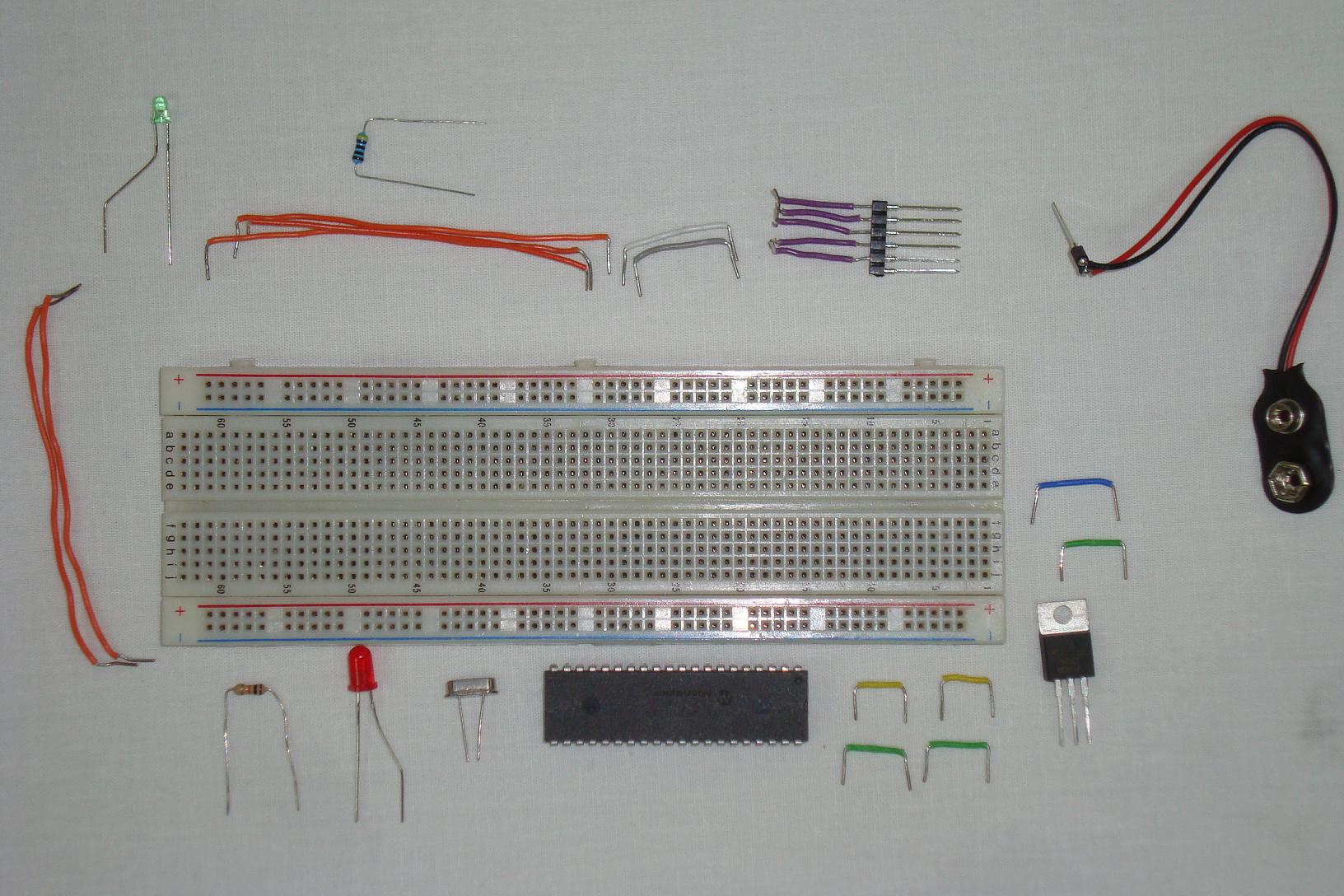
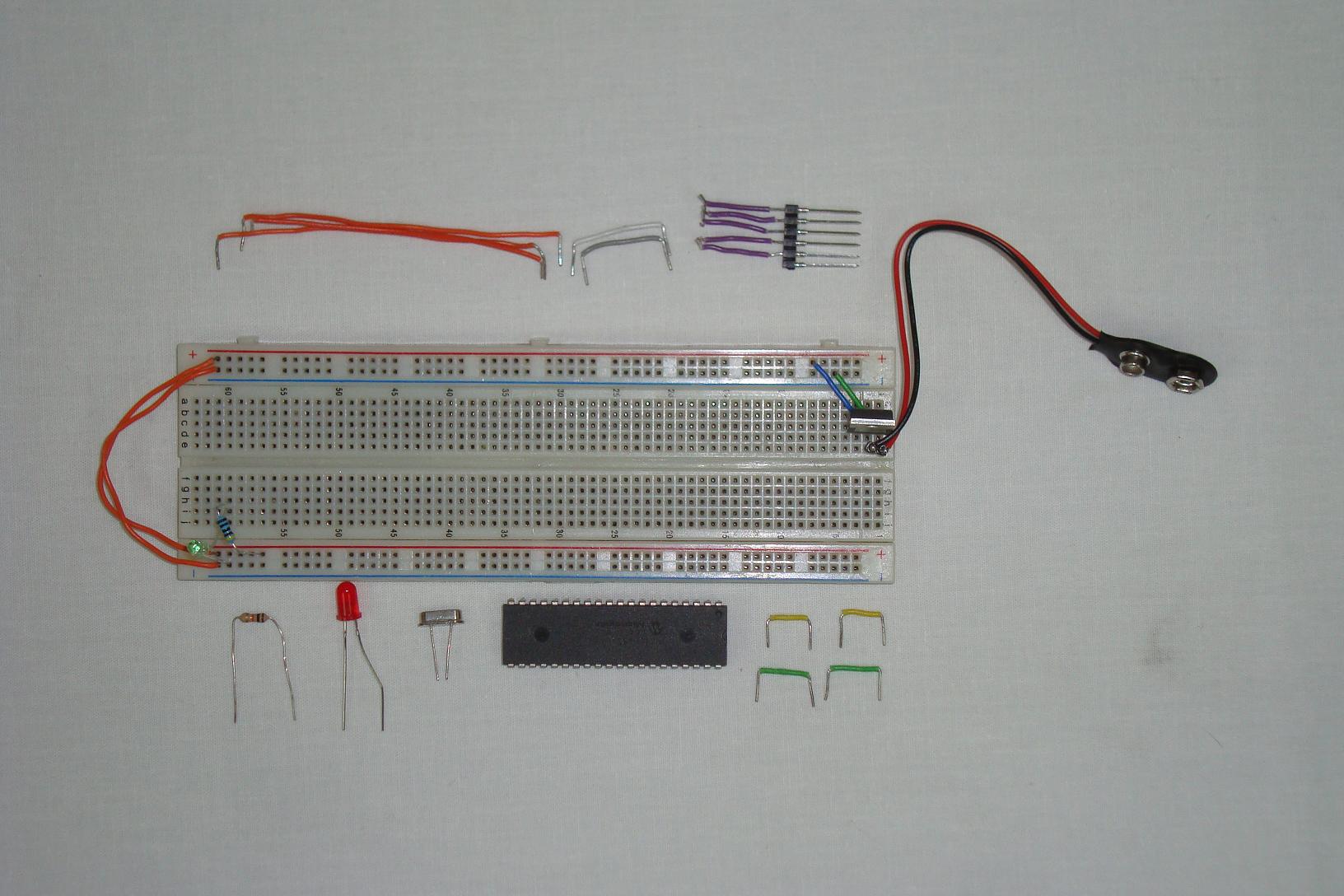
First we'll start out with all of the parts on the table, ready to be assembled. Make sure you have all the parts like I do and then get started building!
·First the +9v connector is connected to the 7805, with a power LED and resistor.

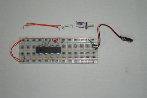
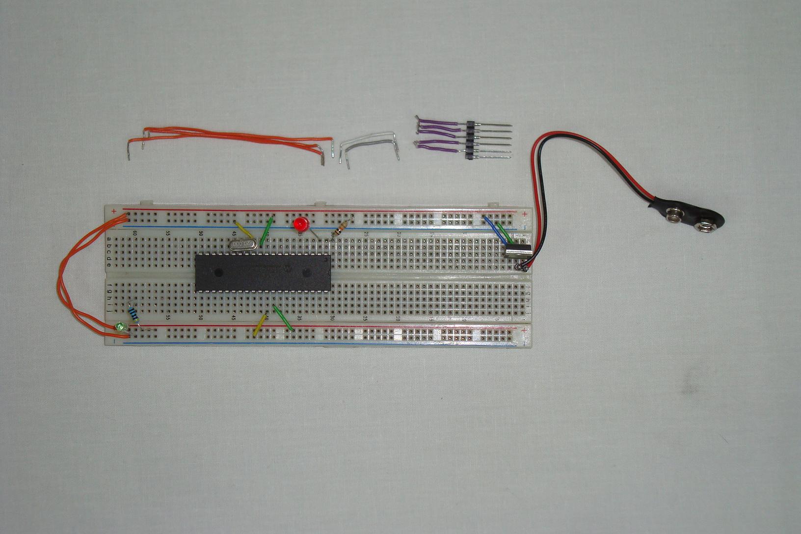
·Next the PIC is added. Power and ground are connected to the pic, along with the 10k resistor to power, and the crystal to pins 13 and 14. The red output LED is also connected to Pin2.
·The final step is building the programming connection port.
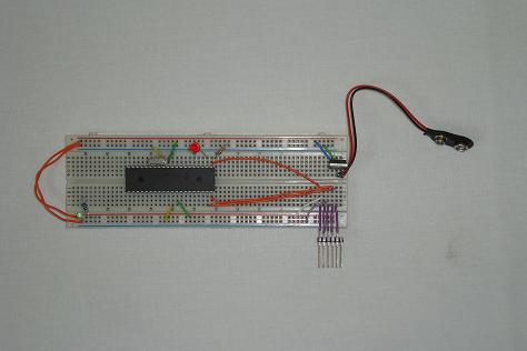
·The hardware is finished and ready to be programmed with some software to blink that red LED.
In this hardware section we will assemble the circuit seen in the schematic step by step so that you can easily follow along and assemble the circuit yourself. Please note that I added a single resistor and LED to power and ground so that I can tell when the power is successfully connected. This small power LED circuit isn't shown in the schematic.
Building The Circuit
First we'll start out with all of the parts on the table, ready to be assembled. Make sure you have all the parts like I do and then get started building!
·First the +9v connector is connected to the 7805, with a power LED and resistor.
·Next the PIC is added. Power and ground are connected to the pic, along with the 10k resistor to power, and the crystal to pins 13 and 14. The red output LED is also connected to Pin2.
·The final step is building the programming connection port.
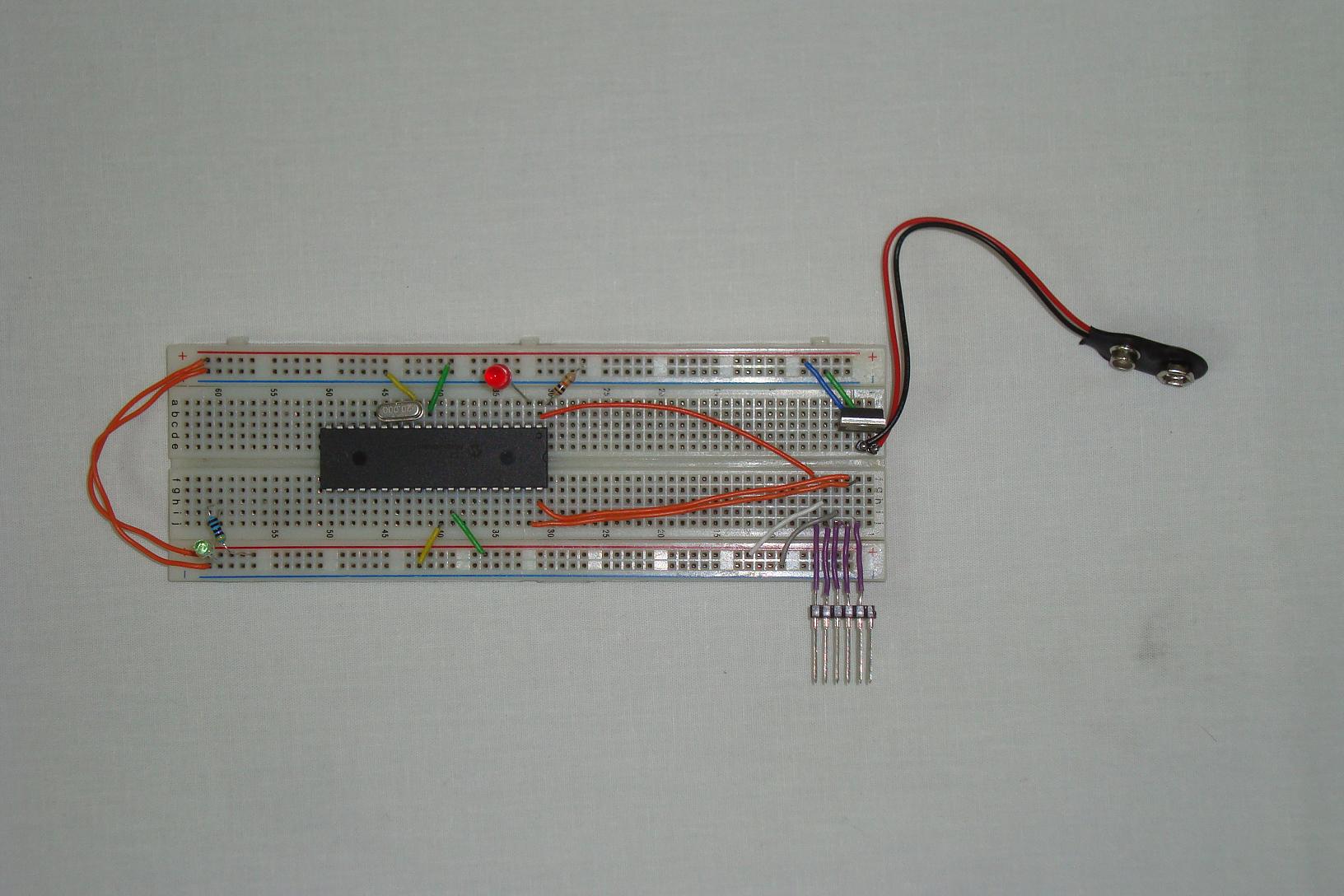
·The hardware is finished and ready to be programmed with some software to blink that red LED.