The H-Bridge
The original concept of the H-Bridge was being able to control the direction a motor was going. Forward or backward. This was achieved by managing current flow through circuit elements called transistors. The formation looks like an H and that's where it gets the name H-Bridge. Here is what it looks like:
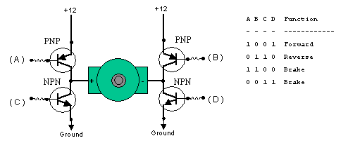
The picture above illustrates the 4 base cases that we can get out of the simple version of an H-Bridge. The two cases that interest us are when A & D are both 1 and when B & C are both 1.
When A & D are 1 current from the battery will flow from point A through the motor to D's ground. However for the case when B & C are both 1, current will flow in the opposite direction from B through the motor to C's ground.
The L298HN Motor Driver
To the right you'll see a sample of what the H-Bridge we'll be working with looks like with each pin labeled. For a complete description of what each pin does check out the datasheet at st.com.
The advantage that the HN offers is that all the extra diodes typically necessary with a standard L298 circuit are already internally in the chip. It saves us as designers an extra element for the motor control circuit.
Varying DC Motor Speed
Pins 5 & 7 in the chip pinout above are inputs 1 & 2 respectively. These inputs take what is called a PWM input. The frequency of the PWM is dependant upon the motor. For our motor we'll use a 1 KHz input frequency. This means the motor speed will be updates 1 thousands times a second. The duty cycle of the PWM will determine the speed & direction of the motor.
The original concept of the H-Bridge was being able to control the direction a motor was going. Forward or backward. This was achieved by managing current flow through circuit elements called transistors. The formation looks like an H and that's where it gets the name H-Bridge. Here is what it looks like:
The picture above illustrates the 4 base cases that we can get out of the simple version of an H-Bridge. The two cases that interest us are when A & D are both 1 and when B & C are both 1.
When A & D are 1 current from the battery will flow from point A through the motor to D's ground. However for the case when B & C are both 1, current will flow in the opposite direction from B through the motor to C's ground.
LMD18245 Pinout
To the right you'll see a sample of what the H-Bridge we'll be working with looks like with each pin labeled. For a complete description of what each pin does check out the datasheet at st.com.
The advantage that the HN offers is that all the extra diodes typically necessary with a standard L298 circuit are already internally in the chip. It saves us as designers an extra element for the motor control circuit.
Varying DC Motor Speed
Pins 5 & 7 in the chip pinout above are inputs 1 & 2 respectively. These inputs take what is called a PWM input. The frequency of the PWM is dependant upon the motor. For our motor we'll use a 1 KHz input frequency. This means the motor speed will be updates 1 thousands times a second. The duty cycle of the PWM will determine the speed & direction of the motor.