Schematic Overview
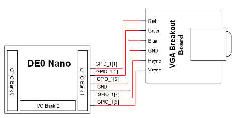
Since we are not actually building the hardware by hand in this project, the electrical schematic is a high level schematic. 5 GPIO pins are chosen from the GPIO_1 bank of the DE0 Nano board and connected to a specific VGA pin. As we get to the source code, we'll map each pin to its appropriate functionality in our code (i.e. Red, Green, Blue, Vsync, Hsync).
View Full Schematic
Schematic Specifics
"DE0 Nano Development Board
This development board has 3 main I/O banks: two 33 pin I/O banks and one 13 pin I/O bank. GPIO_1 is chosen (somewhat randomly) and 5 pins from one side of the connector are connected to the necessary VGA output pins on the breakout board.
"VGA Breakout Board
Even though the VGA connector has 15 pins, we are only interested in making 6 connections: Red, Green, Blue, Ground, Hsync and Vsync. These are the bare minimum connections necessary for driving VGA video output.
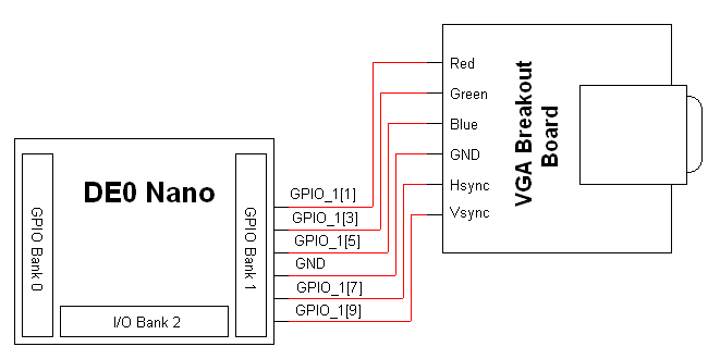