Hardware Design
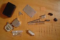
The plastic enclosure seen below wasn't mentioned in the parts list. It's just a generic enclosure you can buy from any electronics distributor or manufacturer.
Here is a picture of the physical & electrical parts we'll need inorder to build the ByteBlaster cable:
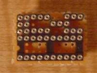
First, we need to decide upon a layout for the circuit. I used sip sockets & standard sips for the resistors to fit into as you can see below. These are soldered onto the board to make sure they don't fall out.
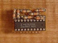
The thing we need to do is to use wirewrap and connect the resistors to the 74LS244 like the schematic shows. There's only 7 resistors, so 7 connections will need to be made. It should look like this (sorry it's kinda fuzzy):
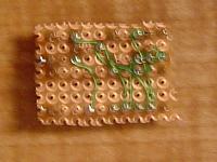
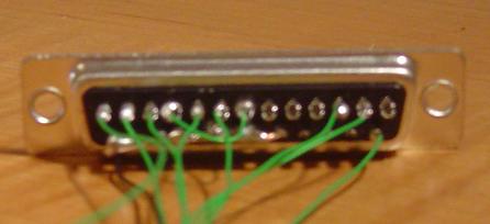
Now we need to connect wires to the DB25 connector. Each strand of wirewrap was soldered into the connector. Not all pins are used as you can see in the picture, the pins that are used are clearly labeled in the schematic.
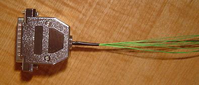
Afterward, assemble the parallel port connector casing around it and now it looks nice and shines!
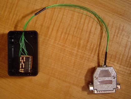
Now, connect the wires coming from the parallel port to the resistors & 74LS244 as shown in the schematic. The pins 18-25 should all be soldered together and connected to ground.
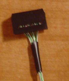
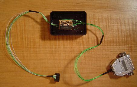
Now that the parallel port is connected to the board, we need to connect the JTAG 10-pin connector to the board. Only 8 wires are actualy connected so this makes our job even easier. The 10-pin header has a unique method of grabbing the wires, so they slide on very easily. Then all that needs to be done is to wirewrap onto the board.
Presto! You've completed making a standard ByteBlaster cable! Not so hard, was it? The next step is optional, however you'll know for sure whether you made any mistakes on the cable (which I'm sure you didn't).
The plastic enclosure seen below wasn't mentioned in the parts list. It's just a generic enclosure you can buy from any electronics distributor or manufacturer.
Here is a picture of the physical & electrical parts we'll need inorder to build the ByteBlaster cable:
First, we need to decide upon a layout for the circuit. I used sip sockets & standard sips for the resistors to fit into as you can see below. These are soldered onto the board to make sure they don't fall out.
The thing we need to do is to use wirewrap and connect the resistors to the 74LS244 like the schematic shows. There's only 7 resistors, so 7 connections will need to be made. It should look like this (sorry it's kinda fuzzy):
Now we need to connect wires to the DB25 connector. Each strand of wirewrap was soldered into the connector. Not all pins are used as you can see in the picture, the pins that are used are clearly labeled in the schematic.
Afterward, assemble the parallel port connector casing around it and now it looks nice and shines!
Now, connect the wires coming from the parallel port to the resistors & 74LS244 as shown in the schematic. The pins 18-25 should all be soldered together and connected to ground.
Now that the parallel port is connected to the board, we need to connect the JTAG 10-pin connector to the board. Only 8 wires are actualy connected so this makes our job even easier. The 10-pin header has a unique method of grabbing the wires, so they slide on very easily. Then all that needs to be done is to wirewrap onto the board.
Presto! You've completed making a standard ByteBlaster cable! Not so hard, was it? The next step is optional, however you'll know for sure whether you made any mistakes on the cable (which I'm sure you didn't).