XBee Modules Theory
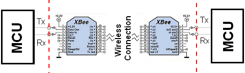
The role of the Xbee module is to be as transparent as possible. It should be as if a wire was connecting the input to the output and connectivity is never lost. While this sounds simple, it's actually a very hard task to accomplish and error correction is a must, which the Xbee's role in offering sound and reliable wireless communication.
The Xbee Pinout
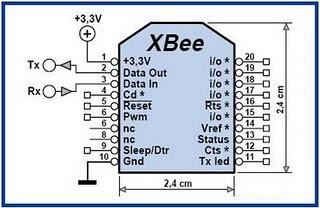
Looking at the Xbee pinout we can see right away the different types of input that can be translated and transmitted wirelessly:
These are some the most common types of signals that are used in electronics and the Xbee offers them all as inputs and outputs.
Standard Xbee Usage
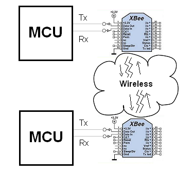
The way we will be using the Xbee in this tutorial is far easier. Striaght out of the box, the Xbee is configured for 9600bps serial communication and so to make things easier, we won't change any of the configuration options. This means we will only be using the Vcc, GND, Din and Dout pins. I will leave it up to you to explore using the other I/O pins available. The picture below illustrates how the Xbee module should act like it is transparent and as if a standard jumper wire connected the microcontroller's Tx and Rx Pins directly to the opposite microcontroller.
Another very important thing to mention about the Xbee modules is that they do have an interactice command interface. This interface allows you to change many options such as the current transmission channel being used, along with many other transmitter/receiver options. See the Xbee module datasheet for more information on the AT command set.
The role of the Xbee module is to be as transparent as possible. It should be as if a wire was connecting the input to the output and connectivity is never lost. While this sounds simple, it's actually a very hard task to accomplish and error correction is a must, which the Xbee's role in offering sound and reliable wireless communication.
Looking at the Xbee pinout we can see right away the different types of input that can be translated and transmitted wirelessly:
- Digital I/O
- Analog I/O (10 bit resolution)
- Pulse with Modulation
- Serial Communication (SPI/RS232/I2C
- CTS/DTR Control Signals
These are some the most common types of signals that are used in electronics and the Xbee offers them all as inputs and outputs.
The way we will be using the Xbee in this tutorial is far easier. Striaght out of the box, the Xbee is configured for 9600bps serial communication and so to make things easier, we won't change any of the configuration options. This means we will only be using the Vcc, GND, Din and Dout pins. I will leave it up to you to explore using the other I/O pins available. The picture below illustrates how the Xbee module should act like it is transparent and as if a standard jumper wire connected the microcontroller's Tx and Rx Pins directly to the opposite microcontroller.
Another very important thing to mention about the Xbee modules is that they do have an interactice command interface. This interface allows you to change many options such as the current transmission channel being used, along with many other transmitter/receiver options. See the Xbee module datasheet for more information on the AT command set.