Transmitter Schematic
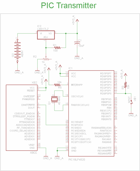
The transmitter schematic consists of 4 main elements. The microcontroller PIC 18LF4520, the XBee wireless module,the SPST push button and the LM317 voltage regulator. When these are combined together
View Full Schematic
Schematic Specifics
Power Supply
The system will need a +3.3v power supply so we will use a LM317 with 2 resistors to create that output voltage.
Microcontroller Circuit
The PIC 18LF4520 is connected to +3.3v power and ground. We use +3.3v because the XBee cannot tolerate +5v!. Also, a 40 MHz crystal is added giving it a 10 MHz instruction frequency.
XBee Module
This module will be used for transmitting the command from the PIC to the receiver system. XBee modules run off of +3.3v so its important not to use a +5v system here!
SPST Push Button
To disting between the 'idle' and 'active' commands sent from the transmitter, a button with a pull-up resistor is used. When the button isn't pressed the RD0 input sees +5v or logic 1. When the button is pressed, the RD0 input sees +0v or logic 0.
Receiver Schematic
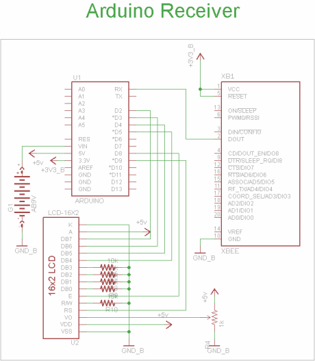
The schematic for the Receiver side of this project contains 3 main components: the Arduino UNO, the 16x2 LCD and the XBee module.
View Full Schematic
Schematic Specifics
Arduino UNO
The Arduino Uno will be connected to a better and then it takes care of the voltage regulation to +5v and +3.3v. The Rx pin will be used to receive the commands from the XBee wireless module.
16x2 LCD Display
This is a standard 16x2 LCD display that runs off of the hitachi hd44780 command set. It will be used to display output to us so that we know the wireless communication is working.
XBee Module
This is the second XBee module that will be used to passing the received command to the Arduino for processing.
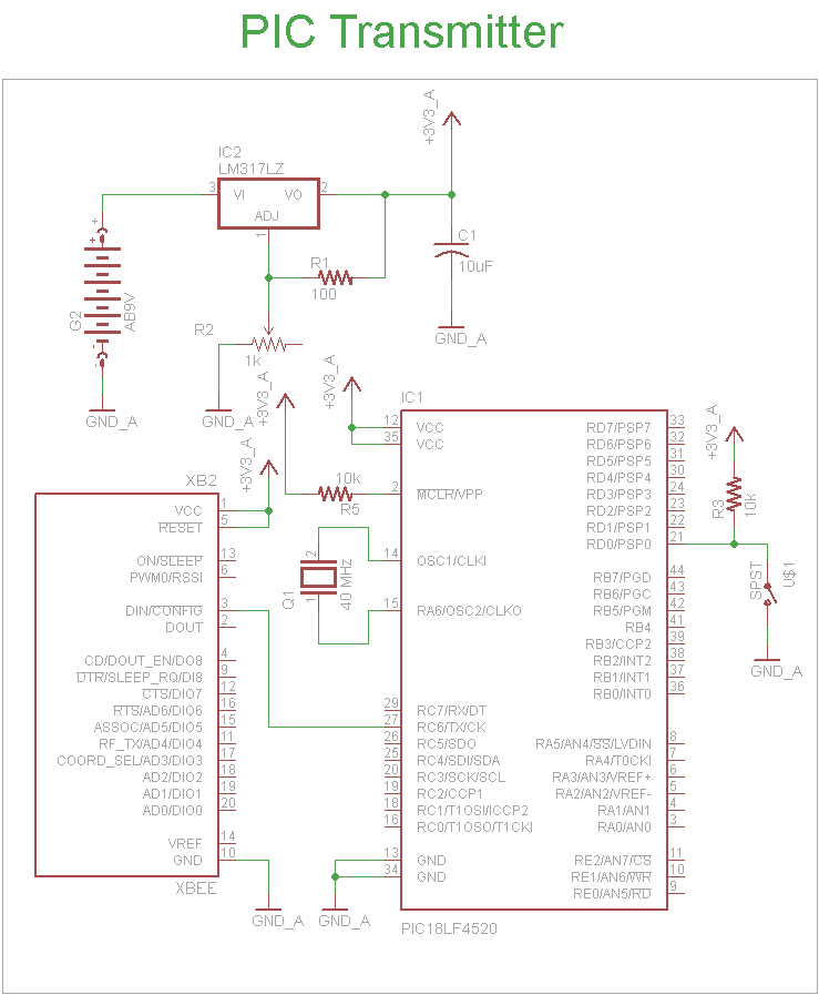
The transmitter schematic consists of 4 main elements. The microcontroller PIC 18LF4520, the XBee wireless module,the SPST push button and the LM317 voltage regulator. When these are combined together
View Full Schematic
Schematic Specifics
Power Supply
The system will need a +3.3v power supply so we will use a LM317 with 2 resistors to create that output voltage.
Microcontroller Circuit
The PIC 18LF4520 is connected to +3.3v power and ground. We use +3.3v because the XBee cannot tolerate +5v!. Also, a 40 MHz crystal is added giving it a 10 MHz instruction frequency.
XBee Module
This module will be used for transmitting the command from the PIC to the receiver system. XBee modules run off of +3.3v so its important not to use a +5v system here!
SPST Push Button
To disting between the 'idle' and 'active' commands sent from the transmitter, a button with a pull-up resistor is used. When the button isn't pressed the RD0 input sees +5v or logic 1. When the button is pressed, the RD0 input sees +0v or logic 0.
Receiver Schematic
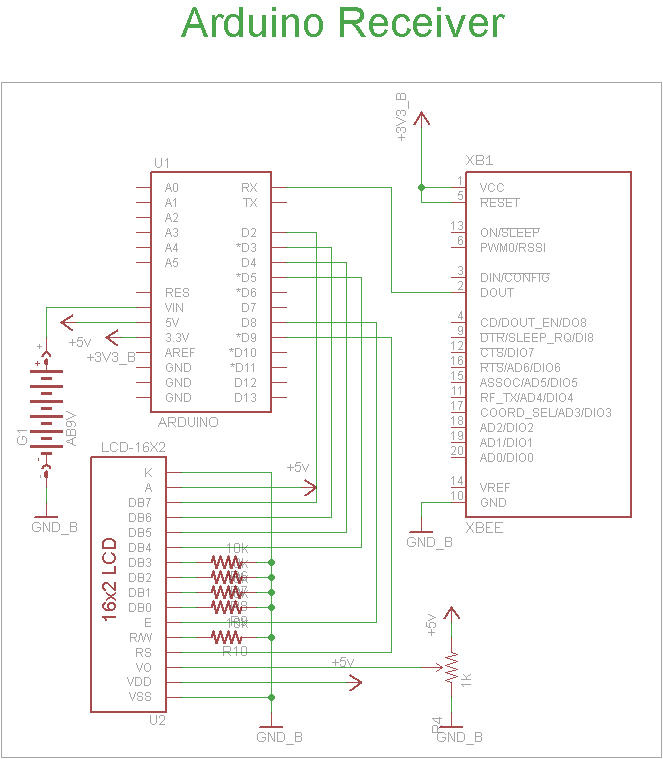
The schematic for the Receiver side of this project contains 3 main components: the Arduino UNO, the 16x2 LCD and the XBee module.
View Full Schematic
Schematic Specifics
Arduino UNO
The Arduino Uno will be connected to a better and then it takes care of the voltage regulation to +5v and +3.3v. The Rx pin will be used to receive the commands from the XBee wireless module.
16x2 LCD Display
This is a standard 16x2 LCD display that runs off of the hitachi hd44780 command set. It will be used to display output to us so that we know the wireless communication is working.
XBee Module
This is the second XBee module that will be used to passing the received command to the Arduino for processing.