Servo Theory


The theory of how servos work hasn't changed since our last article, however we'll go through the basics once more as a quick refresher.
The picture to the right shows a simple PWM: Pulse with Modulation wave. Servos operate off of this principle.
T = 20mS
t = 0.9S -> 2.1S
If we put those values of t & T into the graph we will get a standard analog servo signal. It is important to note that t can vary while T is always the same. T which is 20 miliSeconds defines the period of the wave which also tells us that we are working at a frequency of 50Hz
1 / 0.020 Seconds = 50Hz.
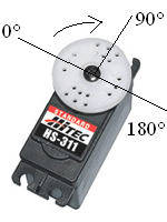
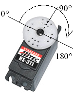
The other portion of the wave that we want to understand is the t part. This is the 'up' part of the wave, meaning a positive +5v is being given out. The rest of the 20mS period a 0v should be output. The variance of 0.9mS->2.1mS is what tells the servo to move & where. Most servos can rotate 90° or 180° and the ones I use can rotate 180°.
So most simply put, we can tell the servos to move to a certain angle with great precision. Some examples for 180° seros....input: t, T and output: angle are seen below.
|
t = 0.9mS T = 20mS Angle = 0° 
|
t = 1.5mS T = 20mS Angle = 90° 
|
t = 2.1mS T = 20mS Angle = 180° 
|