Hardware Design
The hardware design for this project is an extension upon the previous article about controlling a two (or more) servo motors. So don't be surprised if the hardware connections are just as fast, easy and simple as before.
Connecting The Servo
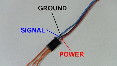
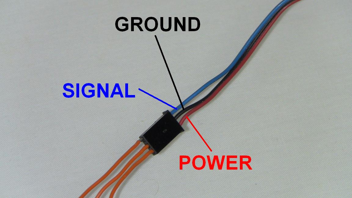
To connect the servo to the arduino I took 3 standard breadboard wires and plugged them into my hobby servo's connector. Notice that the Signal line on my servo's connector is blue and not yellow. Different hobby servo manufacturers use different colors to represent the Signal wire of a hobby servo, but the power and ground wires are always RED and BLACK.
After getting those breadboard wires into the hobby servo connector, connect them to the three spots on the Arduino UNO. Power +5v, Ground GND and Digital Pin 0 (or a digital pin of your choice).

The second set of connections go to the digital pin 1, ground and +3.3v. The picture should show clearly how all connections are made.
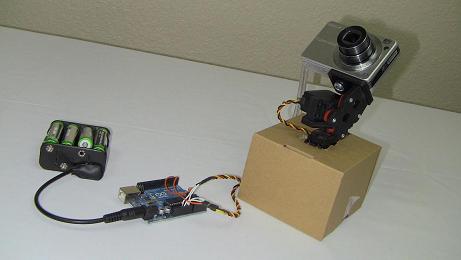
Now that the hardware is complete, let's take a look at the software side of things so that we can get the Arduino programmed and ready to control the servo.
The hardware design for this project is an extension upon the previous article about controlling a two (or more) servo motors. So don't be surprised if the hardware connections are just as fast, easy and simple as before.
Connecting The Servo
To connect the servo to the arduino I took 3 standard breadboard wires and plugged them into my hobby servo's connector. Notice that the Signal line on my servo's connector is blue and not yellow. Different hobby servo manufacturers use different colors to represent the Signal wire of a hobby servo, but the power and ground wires are always RED and BLACK.
After getting those breadboard wires into the hobby servo connector, connect them to the three spots on the Arduino UNO. Power +5v, Ground GND and Digital Pin 0 (or a digital pin of your choice).
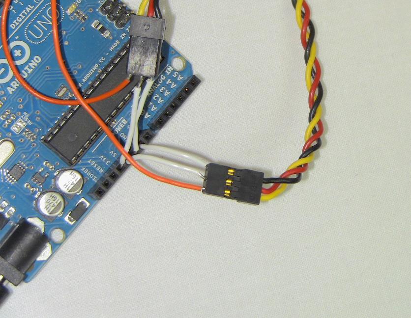
The second set of connections go to the digital pin 1, ground and +3.3v. The picture should show clearly how all connections are made.

Now that the hardware is complete, let's take a look at the software side of things so that we can get the Arduino programmed and ready to control the servo.