Schematic Overview
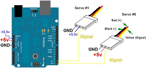
Because the Arduino is already completely built, adding the two servo connections is very simple. Each servo will get a dedicated signal line from the digital outputs of the Arduino and then we'll connect up power and ground to each servo as well. The follow schematic shows the connections made:
View Full Schematic
Schematic Specifics
+5v and +3.3v Servo Power From Arduino
We'll use the +5v and +3.3v pins to power the servo motors. This works for our demonstration about servo control, but if you plan to use servos for real in a project, you will want to connect the power and ground signals directly to your power source. Using the regulated +3.3v and +5v from the Arduino is unwise as motors can suck a lot of current from batteries and that could possibly ruin the voltage regulator used on the Arduino board. So take that caution and keep it in mind.
Servo Signal Connection
Any of the Arduino digital pins can be used to output the driving signal necessary to operate a servo motor. For this demo and article we will use digital pin 0 and digital pin 1. Since these also double as the serial Tx and Rx pins of the Arduino, make sure you disconnect the servo motors from these pins when uploading your program to the Arduino. The servo motors can interrupt that upload process.
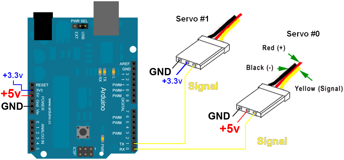