Schematic Overview
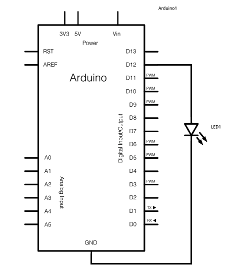
The schematic for this project really only consists of adding a single 5mm LED to one digital output port on the Arduino. The picture below should be fairly self explanatory for how to do it. The main parts in the schematic are the Arduino Uno, 5mm LED and USB Cable.

View Large Schematic
Schematic Specifics
USB Port For Programming
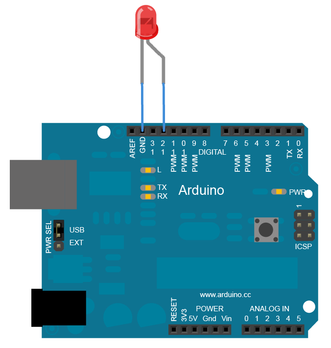
The far left side of the Arduino board (as seen above) has both the DC power jack to supply power for mobile operation and the USB connector for supply power + programming. This USB connector actually connects to a seperate Atmel microcontroller which acts like a translator to convert USB to serial information passed on to our ATMega328 that the Arduino bootloader understands.
5mm LED Addition
The 5mm LED that we will add to the digital output 12 will be used to help prove that we can run both a standard example program and a modified Arduino program. Normally a current limiting resistor should be placed before LEDs, in this case since we won't be using the LED or Arduino in this configuration for months on end, the LED will not be damaged by connecting straight to a digital output.
Arduino Uno Board
This is the platform that I am using, however you are free to use any of the standard Arduino platforms as they all have similar features and you can follow along with this article no matter which one you have.
The schematic for this project really only consists of adding a single 5mm LED to one digital output port on the Arduino. The picture below should be fairly self explanatory for how to do it. The main parts in the schematic are the Arduino Uno, 5mm LED and USB Cable.
View Large Schematic
Schematic Specifics
USB Port For Programming
The far left side of the Arduino board (as seen above) has both the DC power jack to supply power for mobile operation and the USB connector for supply power + programming. This USB connector actually connects to a seperate Atmel microcontroller which acts like a translator to convert USB to serial information passed on to our ATMega328 that the Arduino bootloader understands.
5mm LED Addition
The 5mm LED that we will add to the digital output 12 will be used to help prove that we can run both a standard example program and a modified Arduino program. Normally a current limiting resistor should be placed before LEDs, in this case since we won't be using the LED or Arduino in this configuration for months on end, the LED will not be damaged by connecting straight to a digital output.
Arduino Uno Board
This is the platform that I am using, however you are free to use any of the standard Arduino platforms as they all have similar features and you can follow along with this article no matter which one you have.