The Theory
The theory section for this tutorial will be split up into two sections. This first section will give a quick explanation of how servo motors will be controlled by the PIC and the second theory section will explan the pan and tilt system that will be used for the neck.
Servo Motor Theory
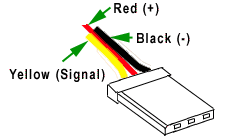
Hi-Tec Servo Motors have three wires coming out of them.
The power & ground wires are hooked directly up to whatever battery or power supply you are using to power the servos. The Signal wire will be hooked up to the microcontroller used to control the servo, in our case the PIC. A noticeable first impression, the servo only requires 1 pin from the pic.
The PWM Signal
The signal that we need to create in order to control the servos is called a Pulse With Modulation signal or PWM for short. The general requirements are:
Frequency: 50Hz
Up-time: 0.9mS ~> 2.1mS
Down-time: 19.1mS ~> 17.9mS
At first glance these definitions & numbers might make little or no sense. So lets look at a simple PWM wave at 50Hz.

So a PWM wave is just a signal that changes between 0 volts & 5 volts (digital logic 0 and 1). We see that the wave is symmetrical; uptime is 10mS & downtime is 10mS which when added together give us the period (10mS + 10mS = 20mS).
The theory section for this tutorial will be split up into two sections. This first section will give a quick explanation of how servo motors will be controlled by the PIC and the second theory section will explan the pan and tilt system that will be used for the neck.
Servo Motor Theory
Hi-Tec Servo Motors have three wires coming out of them.
|
·Red - Power (4.8v-6v) ·Black (Ground) ·Yellow (Signal) |

|
The power & ground wires are hooked directly up to whatever battery or power supply you are using to power the servos. The Signal wire will be hooked up to the microcontroller used to control the servo, in our case the PIC. A noticeable first impression, the servo only requires 1 pin from the pic.
The PWM Signal
The signal that we need to create in order to control the servos is called a Pulse With Modulation signal or PWM for short. The general requirements are:
Frequency: 50Hz
Up-time: 0.9mS ~> 2.1mS
Down-time: 19.1mS ~> 17.9mS
At first glance these definitions & numbers might make little or no sense. So lets look at a simple PWM wave at 50Hz.

So a PWM wave is just a signal that changes between 0 volts & 5 volts (digital logic 0 and 1). We see that the wave is symmetrical; uptime is 10mS & downtime is 10mS which when added together give us the period (10mS + 10mS = 20mS).