Simulating VGA Signals with a PIC Microcontroller
Now that we understand a little more what VGA signals are, we have to devise a method to mimic them with our microcontroller. We use a 4 MHz Ceramic Resonator and so this means each PIC assembly instruction will take 1 uS.
Each line will have the same output of data & horizontal sync. The code will look something similar to this:
Data ;1 uS
Data ;2 uS
Data ;3 uS
Data ;4 uS
..
..
Data ;23 uS
Data ;24 uS
Data ;25 uS
Hsync_0 ;26 uS
Hsync_0 ;27 uS
Hsync_1 ;28 uS
Hsync_1 ;29 uS
Hsync_1 ;30 uS
Hsync_0 ;31 uS
Repeat ;32 uS
This output of data & horizontal sync occurs 480 times. But since the microcontroller is limited to the speed of 1 uS for every assembly instruction the resolution becomes 25x480. At first glass this seems horrid but as we continue we find that it is still useable.
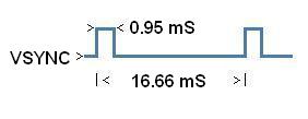
After 480 lines like the above pseudocode we do a vertical sync. It is imperative that the horizontal sync occur as the time approaches 16.66 mS inorder to keep with the 60 Hz refresh rate.
When the time comes to iniate a vertical sync it is just a matter of setting the vsync pin hooked to the monitor to a logic high (+5v) for 0.95 mS. The rest of the
time it is a logic low (+0v).
VGA Image Displayed
The data output from the microcontroller on each line is either a logic high (+5v) or a logic low (+0v). Depending on the color the SPTT switch is hooked onto, the text/graphic will be displayed in Red, Green or Blue. The primitive nature of the microcontroller we're using doesn't allow for various intensities of the colors. We are able to get either 100% color intesity with a logic high +5v or 0% color intesity with a logic low +0v (Black).
The images to be displayed on the screen in this project will all be predefined in the programming code. They are no where near bitmap quality, but just simple text "Ready", a triangle, square, X and circle. I had originally intended to make a psx controller give input to the test box but never implemented that due to the fact that I ran out of spare time inbetween the video refreshes. Each of the 4 buttons on the box will change the screen from the "Ready" display state to one of the pictures (square, x, circle or triangle). There is also a simple on/off SPDT switch that lets current flow through the system when turned 'on'.
Now that we understand a little more what VGA signals are, we have to devise a method to mimic them with our microcontroller. We use a 4 MHz Ceramic Resonator and so this means each PIC assembly instruction will take 1 uS.
Each line will have the same output of data & horizontal sync. The code will look something similar to this:
Horizontal Sync Diagram:
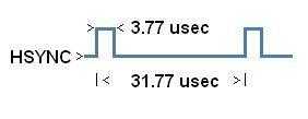
You may notice in the code it runs 32 uS and in the above diagram it runs 31.77 uS. This may seem minute at first glance but since there are 480 lines the .23 uS discrepency alters the end frequency significantly. To remedy this we will have to alter our horizontal & vertical sync times as you will see later in the software.
You may notice in the code it runs 32 uS and in the above diagram it runs 31.77 uS. This may seem minute at first glance but since there are 480 lines the .23 uS discrepency alters the end frequency significantly. To remedy this we will have to alter our horizontal & vertical sync times as you will see later in the software.
Data ;2 uS
Data ;3 uS
Data ;4 uS
..
..
Data ;23 uS
Data ;24 uS
Data ;25 uS
Hsync_0 ;26 uS
Hsync_0 ;27 uS
Hsync_1 ;28 uS
Hsync_1 ;29 uS
Hsync_1 ;30 uS
Hsync_0 ;31 uS
Repeat ;32 uS
This output of data & horizontal sync occurs 480 times. But since the microcontroller is limited to the speed of 1 uS for every assembly instruction the resolution becomes 25x480. At first glass this seems horrid but as we continue we find that it is still useable.
After 480 lines like the above pseudocode we do a vertical sync. It is imperative that the horizontal sync occur as the time approaches 16.66 mS inorder to keep with the 60 Hz refresh rate.
Horizontal Sync Diagram:
VGA Image Displayed
The data output from the microcontroller on each line is either a logic high (+5v) or a logic low (+0v). Depending on the color the SPTT switch is hooked onto, the text/graphic will be displayed in Red, Green or Blue. The primitive nature of the microcontroller we're using doesn't allow for various intensities of the colors. We are able to get either 100% color intesity with a logic high +5v or 0% color intesity with a logic low +0v (Black).
The images to be displayed on the screen in this project will all be predefined in the programming code. They are no where near bitmap quality, but just simple text "Ready", a triangle, square, X and circle. I had originally intended to make a psx controller give input to the test box but never implemented that due to the fact that I ran out of spare time inbetween the video refreshes. Each of the 4 buttons on the box will change the screen from the "Ready" display state to one of the pictures (square, x, circle or triangle). There is also a simple on/off SPDT switch that lets current flow through the system when turned 'on'.