Schematic Overview
Luckily the schematic for this project is plain & simple. There are actually very few electronic components necessary for this project as the PIC Microcontroller is the powerhouse doing most the work. The few components necessary like, buttons, switches & power circuit are trivial forms of I/O which makes understanding how the project works even easier.

View Full Schematic
Schematic Specifics
Power Circuit
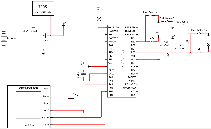
The power circuit is just a 9v Battery hooked up to the LM7805 with a 1uF capacitor hooked to output & ground of the LM7805 to keep a steady 5v DC.
Buttons & Pull-up Resistors
The SPST buttons are tied to ground so when the button is pushed the I/O pin it is attached to is effectively tied to ground. To avoid having a short circuit when the button is pushed, 4.7KΩ or 10KΩ pull-up resistors are used.
SPTT Switch
The SPTT Switch is a non-standard 3 way switch. It can be substituted with any other type of button(s) or switch(es) that will allow 1 input to go to one of 3 outputs. It is optional but you can just tie the wire directly from the PIC to one of the the CRT R/G/B inputs. It's just a matter of which color will display, Red, Green or Blue.
MCLR*/Vpp - Pin 1 on the PIC
This is tied high (logic 1; +5v) once again using a pull-up resistor. Pin 1 is effectively a reset pin. The PIC will restart-Memory Clear-when this pin is low (logic 0, +0v). For this project I did not include a reset button so I just have the pin tied high always, so the PIC will always be running as long as it is powered.
Luckily the schematic for this project is plain & simple. There are actually very few electronic components necessary for this project as the PIC Microcontroller is the powerhouse doing most the work. The few components necessary like, buttons, switches & power circuit are trivial forms of I/O which makes understanding how the project works even easier.
View Full Schematic
Schematic Specifics
Power Circuit
The power circuit is just a 9v Battery hooked up to the LM7805 with a 1uF capacitor hooked to output & ground of the LM7805 to keep a steady 5v DC.
Buttons & Pull-up Resistors
The SPST buttons are tied to ground so when the button is pushed the I/O pin it is attached to is effectively tied to ground. To avoid having a short circuit when the button is pushed, 4.7KΩ or 10KΩ pull-up resistors are used.
SPTT Switch
The SPTT Switch is a non-standard 3 way switch. It can be substituted with any other type of button(s) or switch(es) that will allow 1 input to go to one of 3 outputs. It is optional but you can just tie the wire directly from the PIC to one of the the CRT R/G/B inputs. It's just a matter of which color will display, Red, Green or Blue.
MCLR*/Vpp - Pin 1 on the PIC
This is tied high (logic 1; +5v) once again using a pull-up resistor. Pin 1 is effectively a reset pin. The PIC will restart-Memory Clear-when this pin is low (logic 0, +0v). For this project I did not include a reset button so I just have the pin tied high always, so the PIC will always be running as long as it is powered.