Mixing The Signals Together
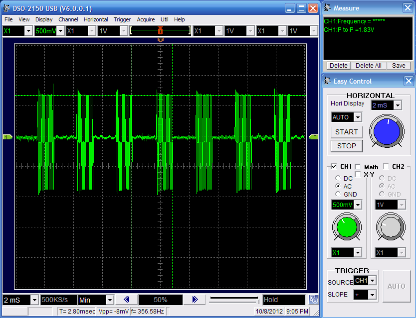
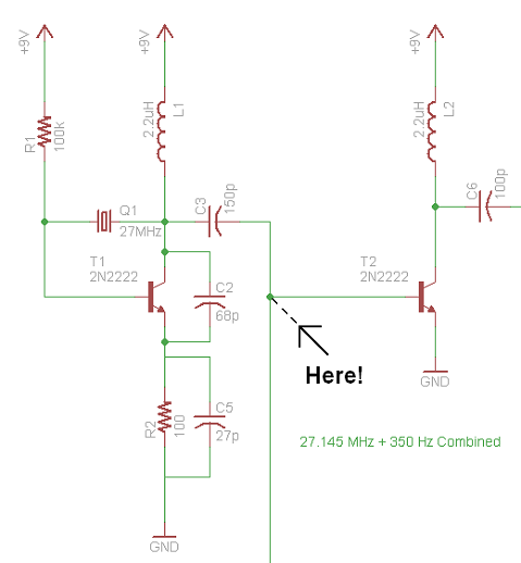
After the carrier 27.145 MHz goes out of the 150pF capacitor it meets with the 555 timer's square wave after the 22k resistors and these two signals mix together (multiply if you prefer). Below you can see the end result of this mixing and where exactly in the schematic it occurs:
In The Schematic:
Measured @ 'Here':

The square wave from the 555 timer is still very visible and the signal is now ready to pass into the base of the transistor and come out looking like what we want to transmit - CW.
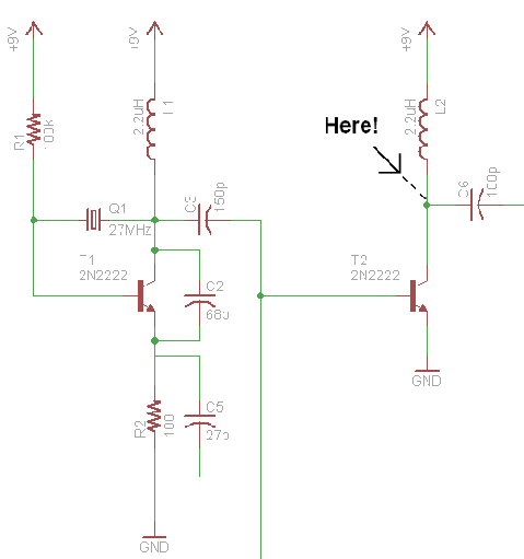
Resulting Continuous Wave Signal
After the mixed signal goes into the transistor, the powerfull on/off switiching from the 555 timer helps produces a nice clean continuous wave output at our carrier frequency and its ready to hit our antenna (after going through 1 final DC blocking cap).
In The Schematic:
Measured @ 'Here':
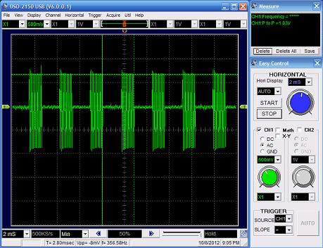
The output is either a gigantic sinwave with 2v peak-to-peak amplitude or basically 0v. The spacing between on/off transitions is in-line with our original 350 Hz signal. So now let's do some power measurements to see how 'powerful' our transmitter actually is!
After the carrier 27.145 MHz goes out of the 150pF capacitor it meets with the 555 timer's square wave after the 22k resistors and these two signals mix together (multiply if you prefer). Below you can see the end result of this mixing and where exactly in the schematic it occurs:
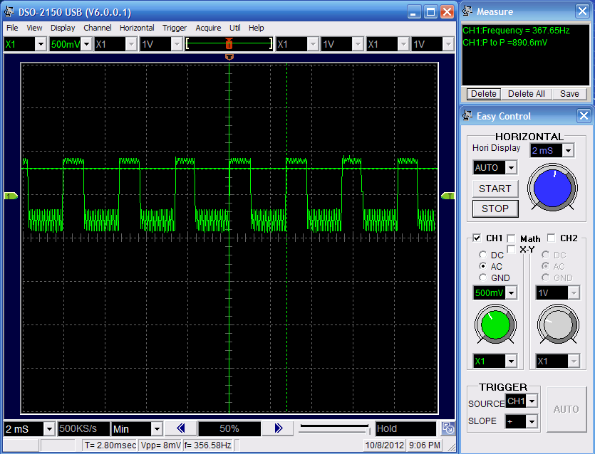
The square wave from the 555 timer is still very visible and the signal is now ready to pass into the base of the transistor and come out looking like what we want to transmit - CW.
Resulting Continuous Wave Signal
After the mixed signal goes into the transistor, the powerfull on/off switiching from the 555 timer helps produces a nice clean continuous wave output at our carrier frequency and its ready to hit our antenna (after going through 1 final DC blocking cap).
Measured @ 'Here':