Theory of Operation
Instead of focusing on the mathematical and raw theoretical side of this simple pyro RF transmitter, we'll be focusing on the elements in each of the stages. The math of how/why this circuit actually works is horridly ugly and way too complicated...so it's funner (for me) to just build and get a 'feeling' for what works and why and where and how.
So let's take some time to go through the schematic step by step to understand each part of the circuit, what it's purpose is and what the signals look like at specific important points. We will go through 3 sections, first taking a look at how the signals we want to transmit are generated, then moving on to see how those signals look when we finally want to transmit them and then finally we'll look at some measurements of the power output of the transmitter.
Carrier Frequency Generation
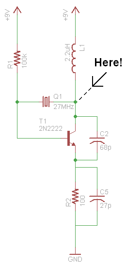
Before we can do anything for this transmitter, we need to generate the signals that we'll be transmitting. So first, looking back at the schematic, here is the part of the circuit that gets the crystal oscillator going:
In The Schematic:
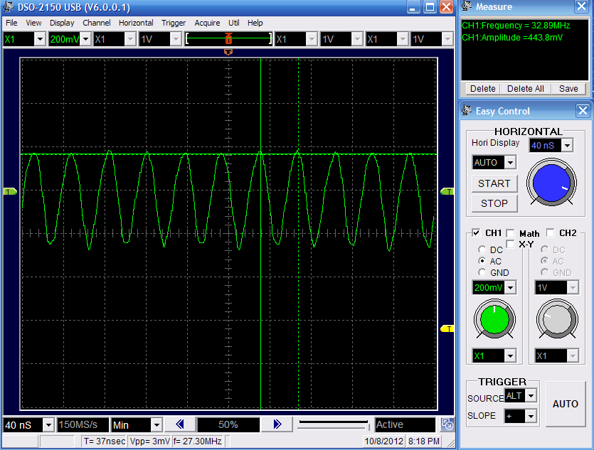
Measured @ 'Here':

Above you can see that the circuit outputs a sin-wave at the frequency we're looking for. Because there is no filtering many harmonic frequencies are present that skew our results slightly, but this signal will work.
On/Off Signal Generation
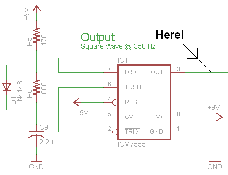
The next signal that we want to generate is the lower frequency on/off 'digital' signal. We use a simple 555 timer to do that with the configuration seen below:
In The Schematic:
Measured @ 'Here':
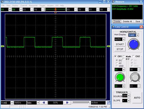
The output is a solid square wave, just as we would expect to see. Now, let's see what happens when these two signals are mixed together!
Instead of focusing on the mathematical and raw theoretical side of this simple pyro RF transmitter, we'll be focusing on the elements in each of the stages. The math of how/why this circuit actually works is horridly ugly and way too complicated...so it's funner (for me) to just build and get a 'feeling' for what works and why and where and how.
So let's take some time to go through the schematic step by step to understand each part of the circuit, what it's purpose is and what the signals look like at specific important points. We will go through 3 sections, first taking a look at how the signals we want to transmit are generated, then moving on to see how those signals look when we finally want to transmit them and then finally we'll look at some measurements of the power output of the transmitter.
Carrier Frequency Generation
Before we can do anything for this transmitter, we need to generate the signals that we'll be transmitting. So first, looking back at the schematic, here is the part of the circuit that gets the crystal oscillator going:
Above you can see that the circuit outputs a sin-wave at the frequency we're looking for. Because there is no filtering many harmonic frequencies are present that skew our results slightly, but this signal will work.
On/Off Signal Generation
The next signal that we want to generate is the lower frequency on/off 'digital' signal. We use a simple 555 timer to do that with the configuration seen below:
Measured @ 'Here':
