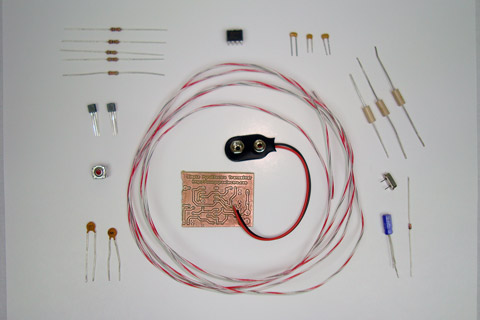
PCB Assembly
With our PCB ready to go, now we will solder all the parts into the board. So get all your parts together as I have below:
·First solder in the 555 timer on/off signal generator. This is easy to test if it's working by pushing the power button on and measuring with any voltage meter.
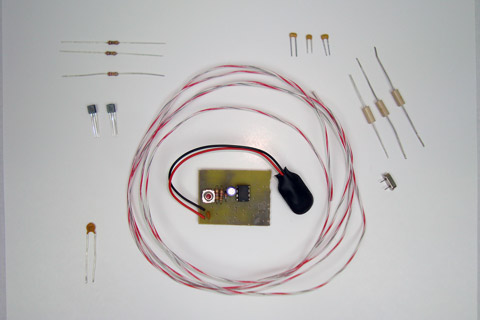
·Now, solder in the 27.145 MHz oscillator circuit.
·The mixing circuit is solderd into the PCB next.
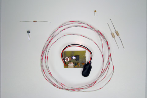
·Finally, the last 10uH inductor and 12" (inch) antenna wire are soldered to the board. Here's a view of the bottom solder joints:
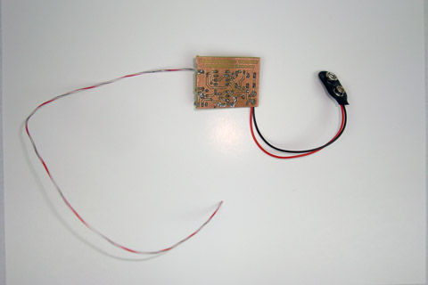
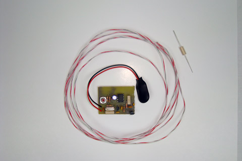
·Similarly, here's a view from the top. Doesn't it look pretty?
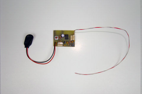
·The transmitter has been built! Now let's go through the theory of how it works.
With our PCB ready to go, now we will solder all the parts into the board. So get all your parts together as I have below:
·First solder in the 555 timer on/off signal generator. This is easy to test if it's working by pushing the power button on and measuring with any voltage meter.
·Now, solder in the 27.145 MHz oscillator circuit.
·The mixing circuit is solderd into the PCB next.
·Finally, the last 10uH inductor and 12" (inch) antenna wire are soldered to the board. Here's a view of the bottom solder joints:
·Similarly, here's a view from the top. Doesn't it look pretty?
·The transmitter has been built! Now let's go through the theory of how it works.