Vsync Schematic Overview
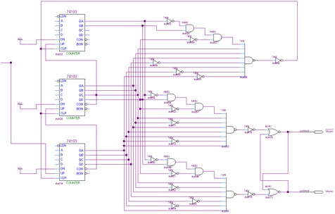
The Vsync generator provides the vertical synchronization pulse to the LCD monitor. It uses 3x 74-193 4 bit counters to count each successful Hsync (horizontal line output) and then triggers Vsync when the count value 601 and 605 are reached. When the count value 628 is reached the counter resets to a value of 0.

View Vsync Schematic
Schematic Specifics
74-193 4-Bit Counters
The Vsync counting circuit uses the same circuit as the Hsync, except the clock input is the Hsync clear signal. This means that the Vsync circuit counts every time a horizontal line finishes outputting.
Count Values and the 7430
601 (0b1001011001), 605 (0b1001011101) and 628 (0b1001110100) are the three unique values that the 7430's are waiting for. 601 and 605 send a pulse to the SR Flip-flop to set or reset the Vsync output signal. A count value of 628 clears the counters back to 0.
Hex Inverters and And Gates
Like in the Hsync circut, some extra hex-inverters and AND gates are used because we need to test more than 8 bits and some of the signals coming in will be 0's, which won't work with the 8-input NAND gate for the 601/605/628 values.
The Vsync generator provides the vertical synchronization pulse to the LCD monitor. It uses 3x 74-193 4 bit counters to count each successful Hsync (horizontal line output) and then triggers Vsync when the count value 601 and 605 are reached. When the count value 628 is reached the counter resets to a value of 0.

View Vsync Schematic
Schematic Specifics
74-193 4-Bit Counters
The Vsync counting circuit uses the same circuit as the Hsync, except the clock input is the Hsync clear signal. This means that the Vsync circuit counts every time a horizontal line finishes outputting.
Count Values and the 7430
601 (0b1001011001), 605 (0b1001011101) and 628 (0b1001110100) are the three unique values that the 7430's are waiting for. 601 and 605 send a pulse to the SR Flip-flop to set or reset the Vsync output signal. A count value of 628 clears the counters back to 0.
Hex Inverters and And Gates
Like in the Hsync circut, some extra hex-inverters and AND gates are used because we need to test more than 8 bits and some of the signals coming in will be 0's, which won't work with the 8-input NAND gate for the 601/605/628 values.