Full Schematic Overview
The full schematic for this project is really, really big so if you want to see it, go ahead and click the picture below. Since the schematic is so big I split the explanation of how things are connected together into three sections. The Hsync Generator, Vsync Generator and Color Generator.
(Note: The 7805 +5v power circuit and power LED are not featured in the schematic.)
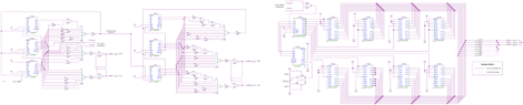
View Full Schematic Hsync Schematic Overview
The Hsync circuit uses 3x 4-bit counters to count up to specific values that trigger the Hsync signal as well as a clear signal to reset the counter value to 0.
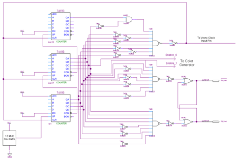
View Hsync Schematic
Schematic Specifics
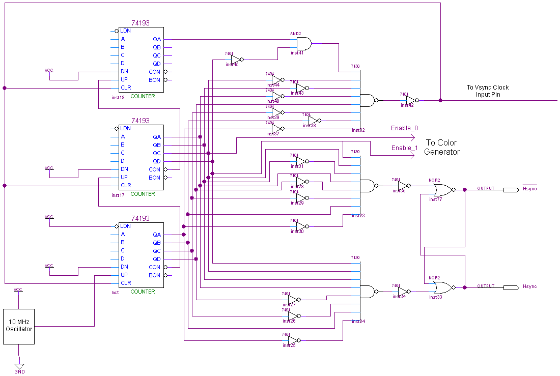
74-193 4-Bit Counters
A 10 MHz crystal oscillator is input to the first 4-bit counter which counts up. The carry bit from the first counter is connected to the 2nd counter so that the 2nd counter will continue counting upward, likewise for the 3rd counter.
Count Values and the 7430
210 (0b11010010), 242 (0b11110010) and 264 (0b100001000) are the three unique values that the 7430 8-input NAND gates are looking for. 210 will trigger the Hsync signal to set to 1, 242 triggers it to reset to 0 and 264 is the clear signal which tells the counters to start counting from 0 again.
Hex Inverters and AND Gates
Some hex inverters are used to make sure the input into the 7430 NAND gate is "11111111" for each of the specific values we want to trigger Hsync and Clear at. AND gates are used whenever the value is larger than 8 bits, since the 7430 maxes out at 8-bits.
Enable_0 and Enable_1 Output
Since the R/G/B color output cannot always be active, we need to make sure it is only enabled when the VGA timing allows for color signals to be active. These two signals are fed into the color generator as color enable signals.
The full schematic for this project is really, really big so if you want to see it, go ahead and click the picture below. Since the schematic is so big I split the explanation of how things are connected together into three sections. The Hsync Generator, Vsync Generator and Color Generator.
(Note: The 7805 +5v power circuit and power LED are not featured in the schematic.)

View Full Schematic
The Hsync circuit uses 3x 4-bit counters to count up to specific values that trigger the Hsync signal as well as a clear signal to reset the counter value to 0.
View Hsync Schematic
Schematic Specifics
74-193 4-Bit Counters
A 10 MHz crystal oscillator is input to the first 4-bit counter which counts up. The carry bit from the first counter is connected to the 2nd counter so that the 2nd counter will continue counting upward, likewise for the 3rd counter.
Count Values and the 7430
210 (0b11010010), 242 (0b11110010) and 264 (0b100001000) are the three unique values that the 7430 8-input NAND gates are looking for. 210 will trigger the Hsync signal to set to 1, 242 triggers it to reset to 0 and 264 is the clear signal which tells the counters to start counting from 0 again.
Hex Inverters and AND Gates
Some hex inverters are used to make sure the input into the 7430 NAND gate is "11111111" for each of the specific values we want to trigger Hsync and Clear at. AND gates are used whenever the value is larger than 8 bits, since the 7430 maxes out at 8-bits.
Enable_0 and Enable_1 Output
Since the R/G/B color output cannot always be active, we need to make sure it is only enabled when the VGA timing allows for color signals to be active. These two signals are fed into the color generator as color enable signals.