Schematic Overview
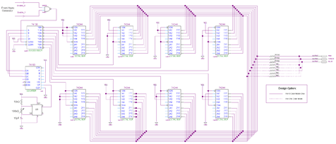
The last part of the schematic is the color generator. A state machine with 8 states is used to output 8 different color signals to the monitor. The design offers up to 256 unique colors to be output, however I only actually wired up enough for 8 unique colors. See the 'dashed lines' in the schematic for how to make 256 color work.
View Color Generator Schematic
Schematic Specifics
"74-193, 555 timer and 74-138
A 4-bit counter is used again to count up, and a standard multivibrator 555 circuit is used as the clock input to the counter. A variable resistor allows for the user to change the speed of the 555 timer clock output. The lower 3 bits of the counter output is input into a 3-8 De-Multiplexer which acts as a state machine select. With each count the de-mux selects a different state.
State Outputs via 74-244 Octal Buffers
8 of these Octable Buffers are used to output different state values. When the 74-138 selects one of the 74-244 buffers, it activates and outputs its hard-wired value to the Red/Green/Blue pins of the VGA connector.
R/G/B Output And Resistor DAC
An 8 resistor DAC is used for anyone who wishes to output one of an array of 256 colors, however I chose to only wire up the 3 most significant bit wires to R/G/B. This gives just enough to offer a unique color output for each of the 8 states.
Enable_0 and Enable_1
These signals are input from the Hsync circuit and act as enable signals for the color output. They make sure that the R/G/B signals are only active when they should be and not all the time.
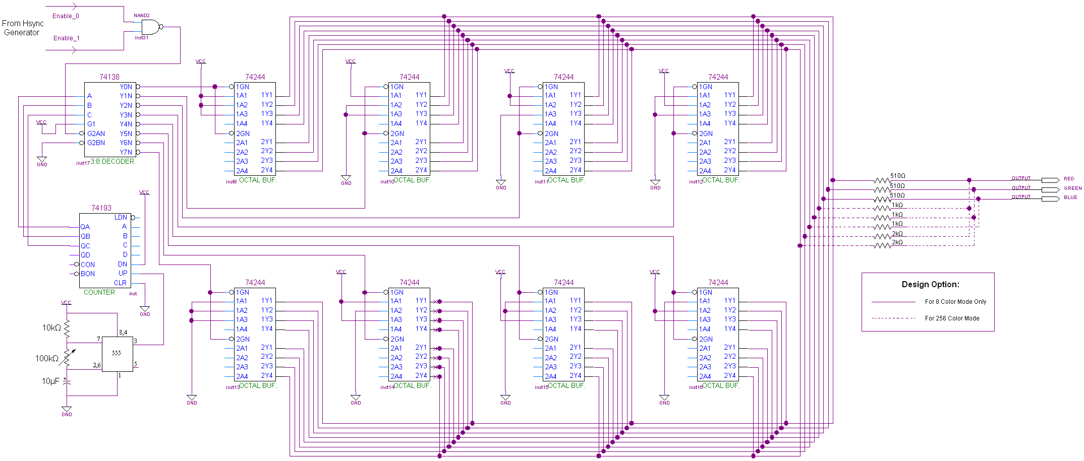