Building The Vsync Circuit
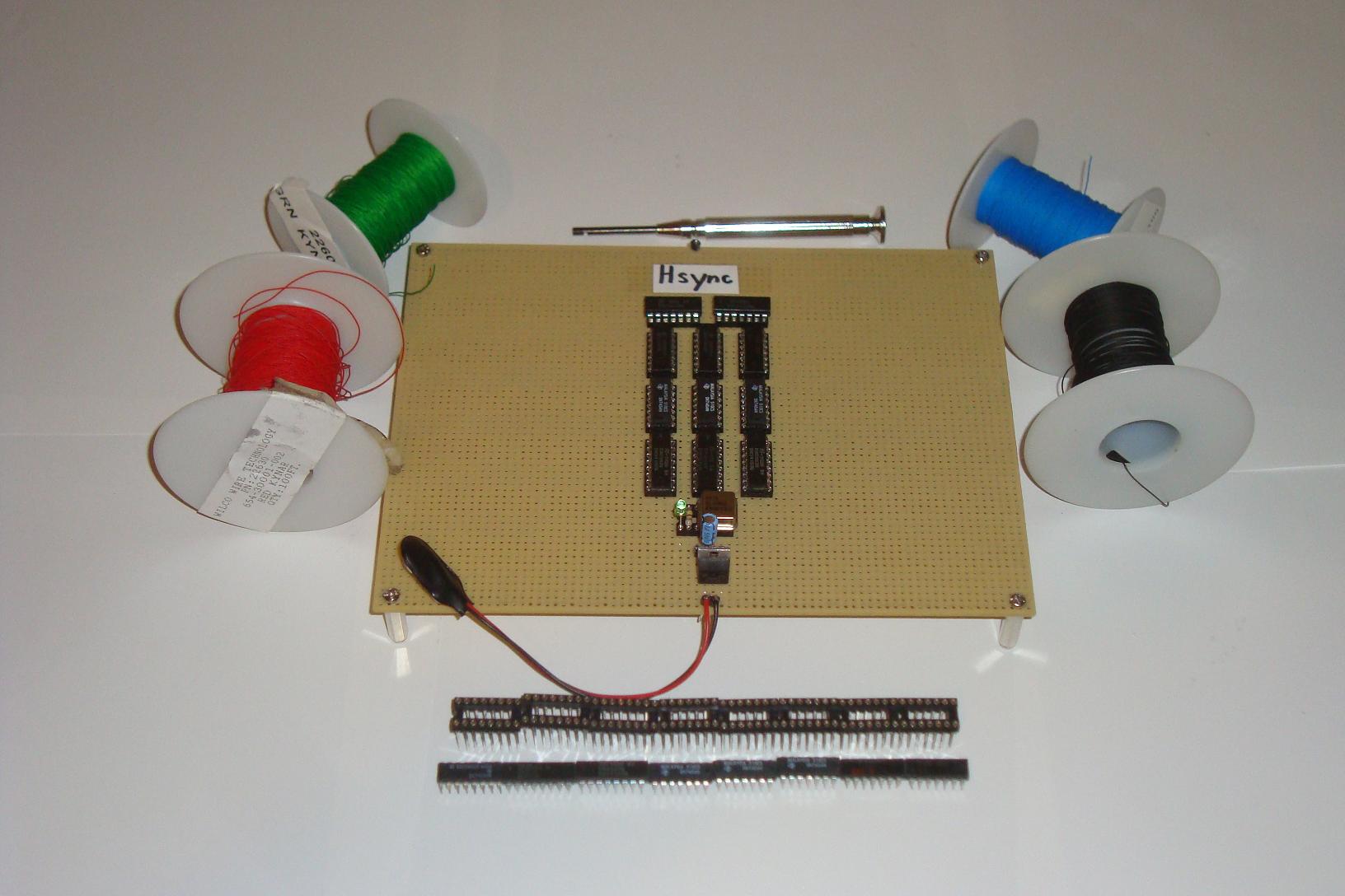
Just like before, gather all of the parts seen in the Vsync schematic. Below you can see a picture of all the parts I used, 9 IC's in total.

·Just like before, layout all your IC sockets and IC's how you want them.
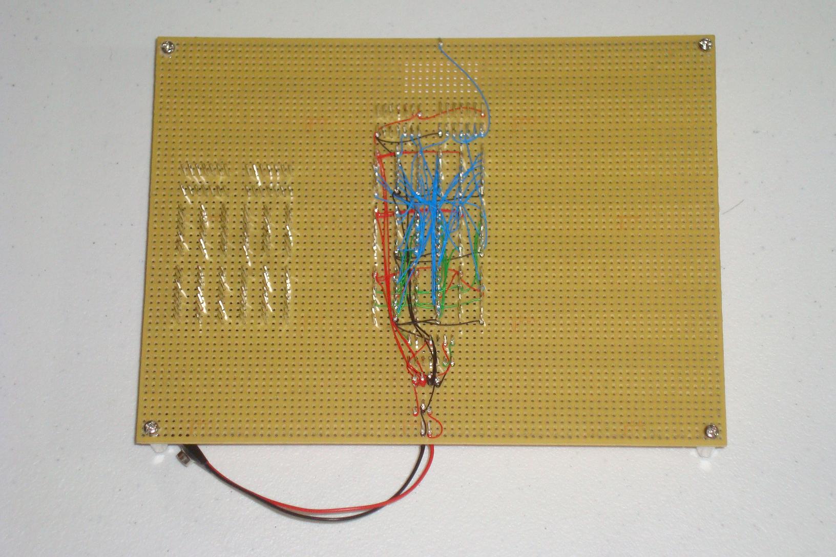
·Now follow the schematic and wire-wrap all the IC's together. Some connections to the Vsync circuit Actually come from the Hsync circuit, so it's ok to cross the boundary.

·To Avoid using an extra IC, I used the 7402 on the Hsync side for the Vsync RS FlipFlop. Other than that, Wire-Wrapping is done!

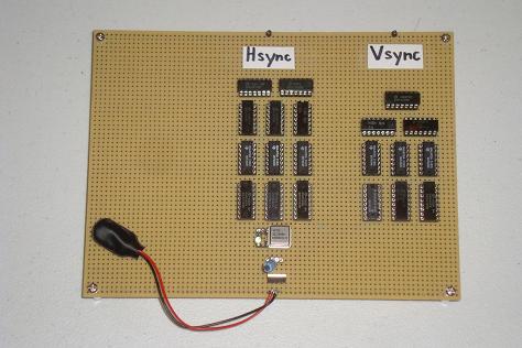
·Vsync circuitry is complete! If things are wired together properly, you can plug Hsync, Vsync and GND to a VGA LCD. It will display nothing, but it will show you that input is detected.
Just like before, gather all of the parts seen in the Vsync schematic. Below you can see a picture of all the parts I used, 9 IC's in total.
·Just like before, layout all your IC sockets and IC's how you want them.
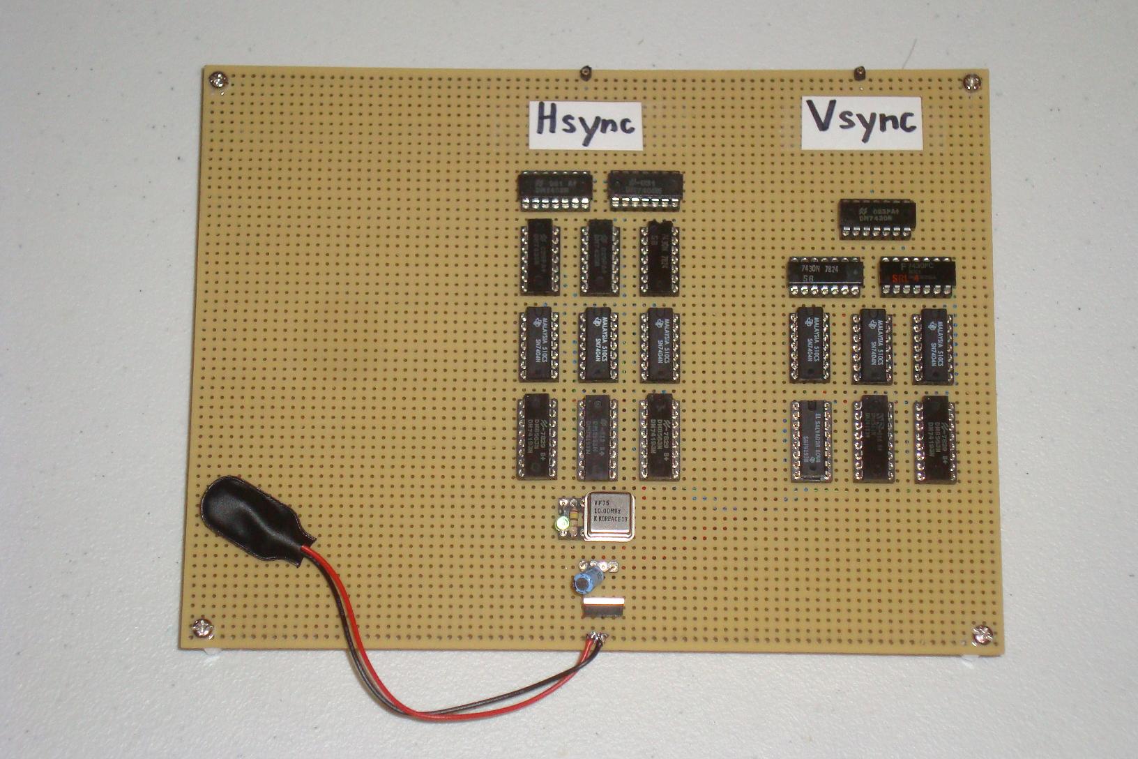
·Now follow the schematic and wire-wrap all the IC's together. Some connections to the Vsync circuit Actually come from the Hsync circuit, so it's ok to cross the boundary.
·To Avoid using an extra IC, I used the 7402 on the Hsync side for the Vsync RS FlipFlop. Other than that, Wire-Wrapping is done!
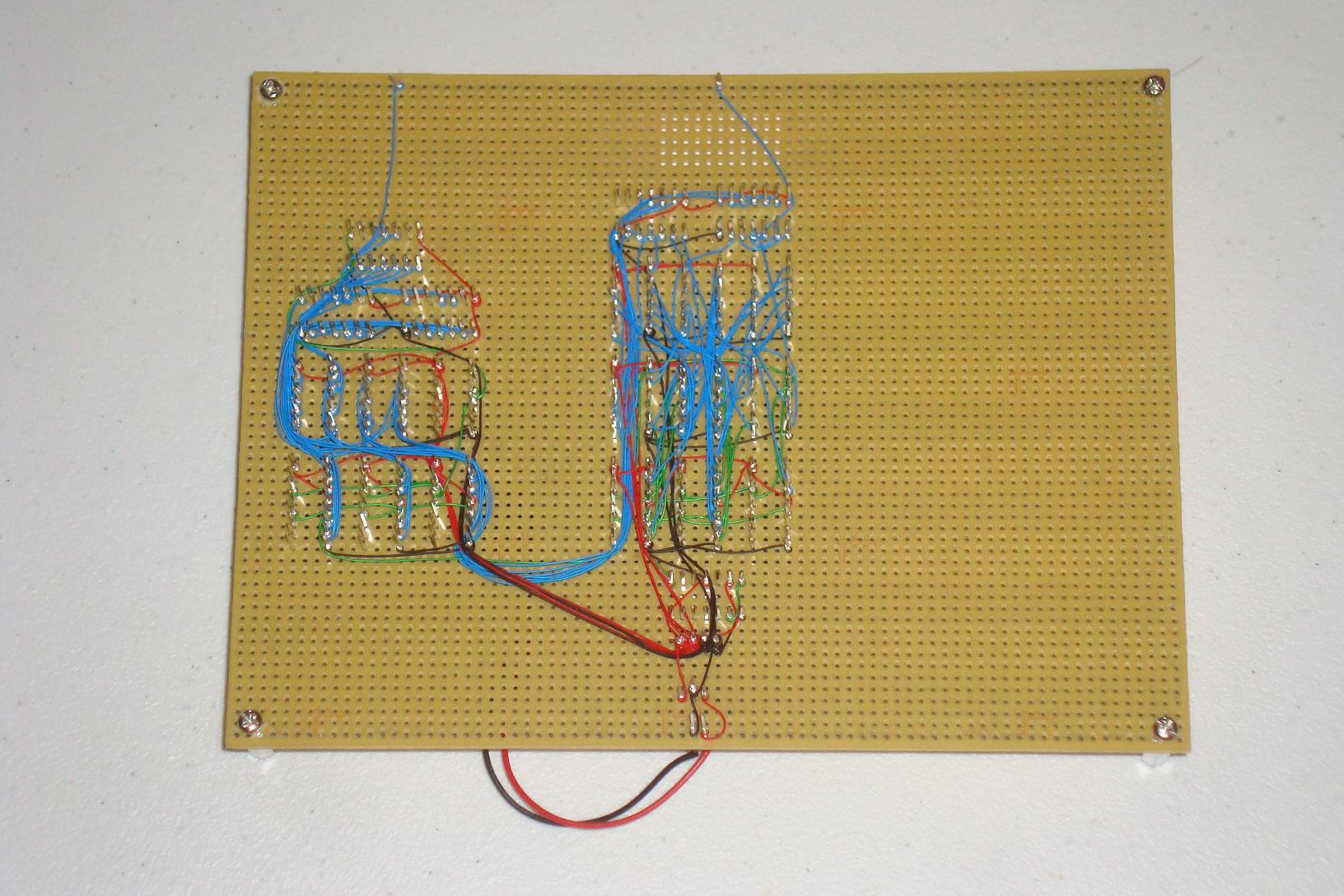
·Vsync circuitry is complete! If things are wired together properly, you can plug Hsync, Vsync and GND to a VGA LCD. It will display nothing, but it will show you that input is detected.