Hardware Design
We just went through the process of how to build the PCB for this project. Now let's focus more on how to actually put everything together. You'll need a soldering iron and some solder for this part.
Assembling The PCB
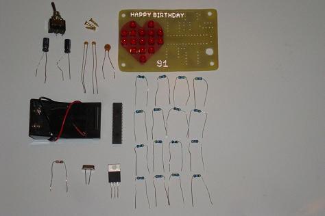
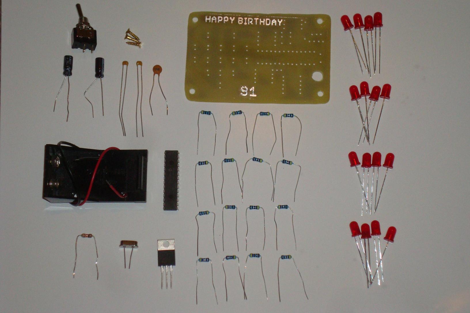
To assemble the PCB, you will need all of the parts nearby. The picture below shows all of the parts needed for this project laid out along side the board.

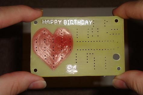
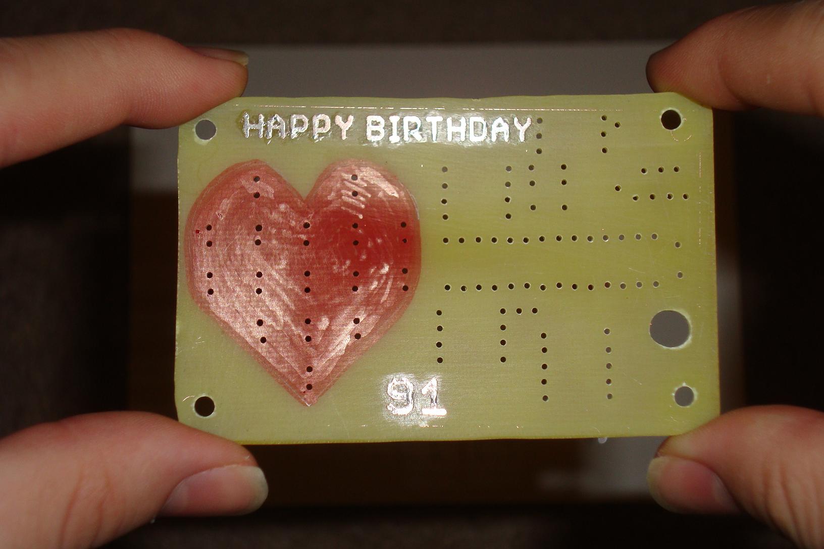
First things first, we need to draw the background heart with a red felt-pen. That will create a nice look to go with the LEDs and really give the feeling that it is a heart.
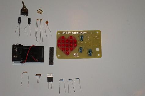
With the heart drawn we'll start soldering in the LEDs.

One by one the LEDs are added until it's time to add the resistors. I like to add these smaller parts first because they're easier to solder in perfectly.
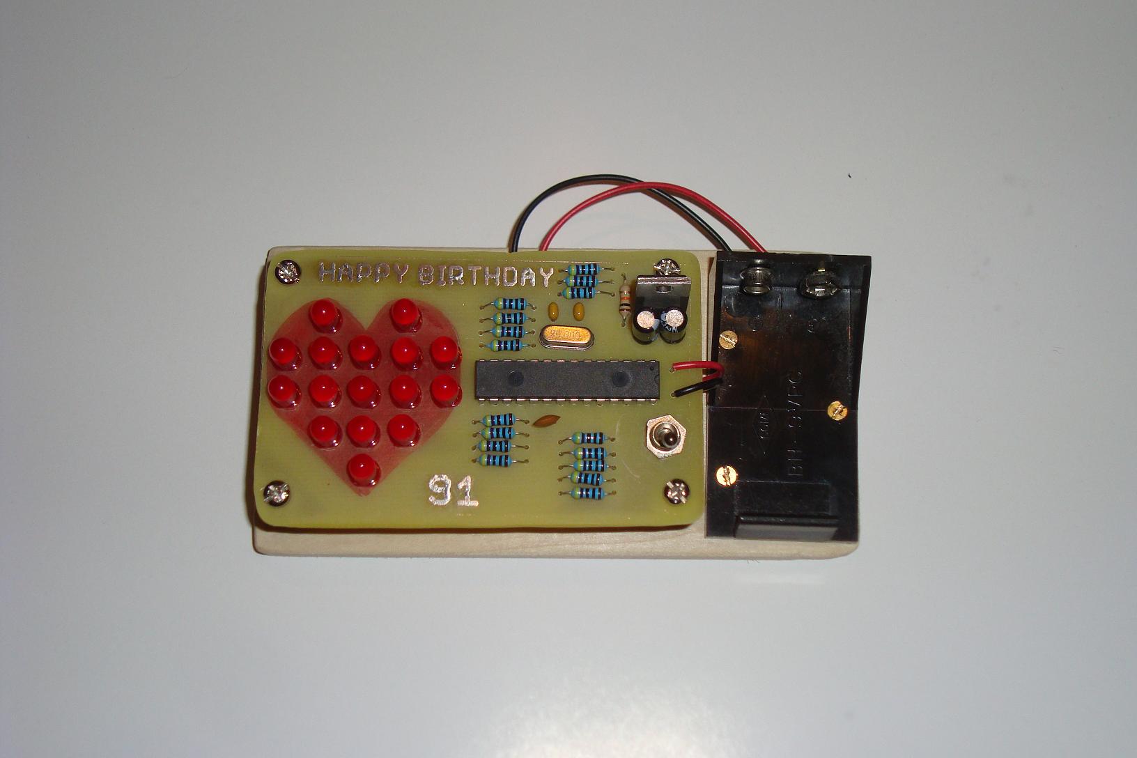
Now the resistors are soldered in, the last few parts that remain are the microcontroller IC, a few caps, the regulator and other small parts. Solder them in.
After all the parts have been soldered to the board, the last few things to be done are mechanical. The stand-offs need to be added and the +9v battery holder screwed into a base.
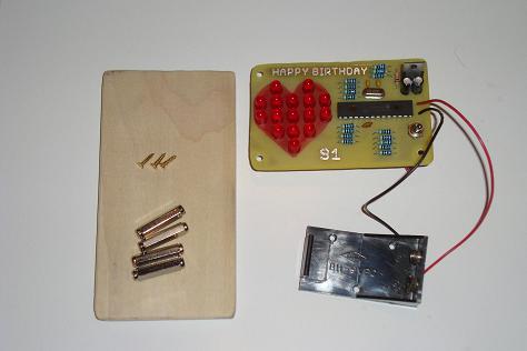
I used a piece of wood with rounded edges to create a base. You could easily use plastic or anything rectangular and sturdy.

After all that hard work on the hardware, it's time to shift gears and get the software written and done.
We just went through the process of how to build the PCB for this project. Now let's focus more on how to actually put everything together. You'll need a soldering iron and some solder for this part.
Assembling The PCB
To assemble the PCB, you will need all of the parts nearby. The picture below shows all of the parts needed for this project laid out along side the board.
First things first, we need to draw the background heart with a red felt-pen. That will create a nice look to go with the LEDs and really give the feeling that it is a heart.
With the heart drawn we'll start soldering in the LEDs.
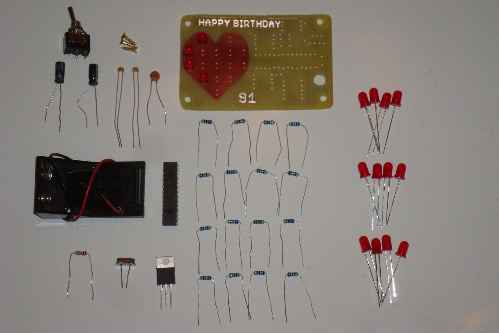
One by one the LEDs are added until it's time to add the resistors. I like to add these smaller parts first because they're easier to solder in perfectly.

Now the resistors are soldered in, the last few parts that remain are the microcontroller IC, a few caps, the regulator and other small parts. Solder them in.

After all the parts have been soldered to the board, the last few things to be done are mechanical. The stand-offs need to be added and the +9v battery holder screwed into a base.
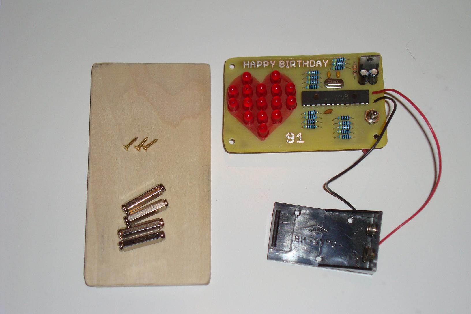
I used a piece of wood with rounded edges to create a base. You could easily use plastic or anything rectangular and sturdy.
After all that hard work on the hardware, it's time to shift gears and get the software written and done.