The schematic for this project is not too terrible, it's mostly connecting the LEDs to current limiting resistors and then to the PIC. Although it might seem that I arbitrarily chose connections for each LED, there's reason for each LED # to connect where it is: it makes the layout process easier for us.
View Full Schematic
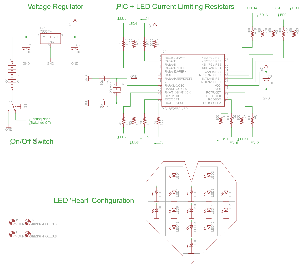
Schematic Specifics
+5v Power Regulator and On/Off Toggle Switch
A 7805 Linear Regulator will be used to regulate the +9v battery down to +5v that the PIC needs to operate. The toggle switch connects the entire circuit to ground allowing current to flow through the circuit, thus turning it on or off.
PIC Microcontroller + 100Ω Resistors
The PIC's general purpose outputs on PORTA, PORTB and PORTC will be used to connect to each individual LED thus giving us maximum control over each LED when programming to tell it what to do. 100Ω current limiting resistors are placed between the general purpose I/O port and the LED so that we don't burn out the PIC or the LED by allowing too much current to flow through the microcontroller's pin or the LED.
LED Heart Shape
The LED's have all been given a numeric designation and a location in the heart so as to create no confusion about what is connected where, and doing this will also make coding the heart a lot easier once we've matched the hardware and software together.
Board Layout Overview
The layout for this board is split into two sections. The left hand side is reserved for the LEDs and heart shape and the right-hand side is where all the electronics will go. Splitting the board into two sides like this gives a nice feeling of symmetry between the fun part and the working part.

View Full Layout
PIC 18F252 + Current Limiting Resistors
As you can see the heart and PIC/resistors are split to two sides of the board so that it's obvious where you should be watching when you turn it on. Resistors are placed strategically so that the routing to LEDs is straight forward and easy to follow.
Heart Shaped LEDs
You can see the rough outline of the LEDs forming a heart shape. It will be much clearer on the board when we draw the red heart in the background. Additionally, I've added some copper to the top layer that says "Happy Birthday" and "91" (my grandma's age now!).
4 Corner Stand-offs
We'll drill 4 holes in the corner for stand-offs to go into and you can see their placement on the top and bottom layers.