Schematic Overview
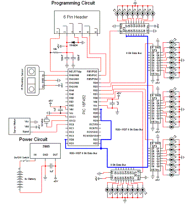
The schematic for this project is much more complicated than previous projects. There are four main features in our design. (1) We will be able to program the pic on the board we develop. (2) We will be controlling a servo. (3) We will be taking data input from an IR Proximity sensor. (4) We will set 36 LEDs to display proper output to respresent what the IR sensor sees.

View Full Schematic
Schematic Specifics
Power Circuit
The power circuit is a 9v Battery hooked up to the LM7805 with a 1uF capacitor hooked to output & ground of the LM7805 to keep a steady 5v DC.
Programming Circuit
The programming circuit is made by hooking up two pins from the PIC to the programmer and allowing the programmer's pin 1 access to the MCLR*/Vpp-Pin1 on the PIC. We put a rectifier diode in there for safety as well.
IR Proximity Sensor
The IR Sensor only uses 1 pic from the pic, PIN 2 - RA0. It will use the analog feature of this pin to get an ADC value as the proximity sensor only outputs analog voltages. This value will tell us the if anything is near the sensor in our enviornment.
LEDs Output
There are 40 LEDs in total. Since each 74HCT373 can control up to 8 leds; 40/8 = 5 we'll need to use 5 74HCT373's to be able to control all 40 LEDs. It is important to notice on the schematic that a common data bus is used between all the 5 chips.
The schematic for this project is much more complicated than previous projects. There are four main features in our design. (1) We will be able to program the pic on the board we develop. (2) We will be controlling a servo. (3) We will be taking data input from an IR Proximity sensor. (4) We will set 36 LEDs to display proper output to respresent what the IR sensor sees.

View Full Schematic
Schematic Specifics
Power Circuit
The power circuit is a 9v Battery hooked up to the LM7805 with a 1uF capacitor hooked to output & ground of the LM7805 to keep a steady 5v DC.
Programming Circuit
The programming circuit is made by hooking up two pins from the PIC to the programmer and allowing the programmer's pin 1 access to the MCLR*/Vpp-Pin1 on the PIC. We put a rectifier diode in there for safety as well.
IR Proximity Sensor
The IR Sensor only uses 1 pic from the pic, PIN 2 - RA0. It will use the analog feature of this pin to get an ADC value as the proximity sensor only outputs analog voltages. This value will tell us the if anything is near the sensor in our enviornment.
LEDs Output
There are 40 LEDs in total. Since each 74HCT373 can control up to 8 leds; 40/8 = 5 we'll need to use 5 74HCT373's to be able to control all 40 LEDs. It is important to notice on the schematic that a common data bus is used between all the 5 chips.