Hardware Design
We're now on to the second part of the hardware design, the digital control! Since this project is all-hardware, no software, we get to use our hands building, soldering and wire-wrapping everything to make it work.
Building The LED Controller
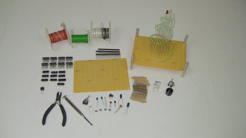
First things first, gather all of the parts together from the parts list, including the LED Christmas tree we already built. We will follow the schematic from here on out.
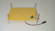
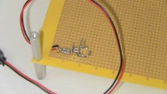
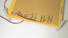
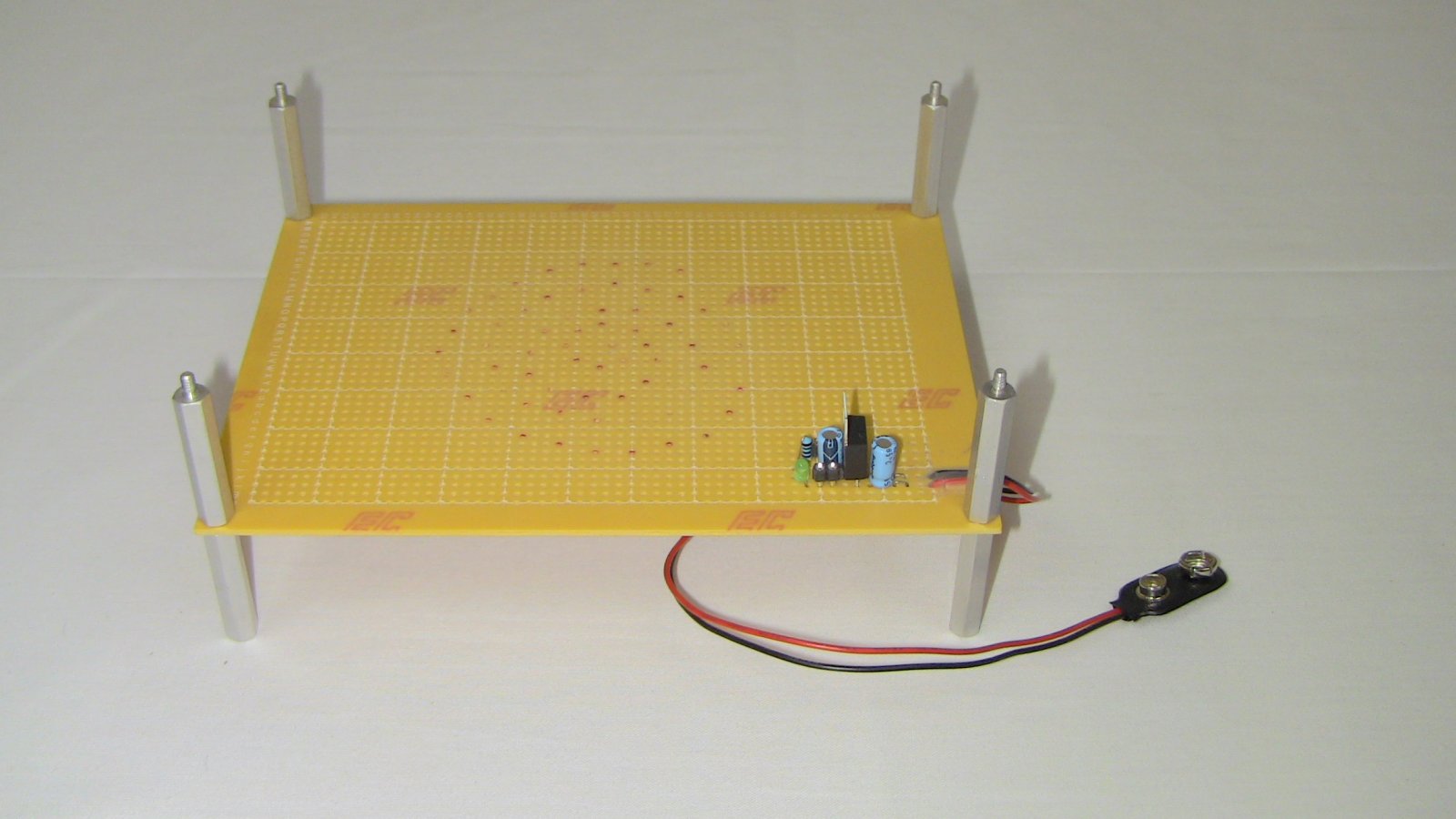
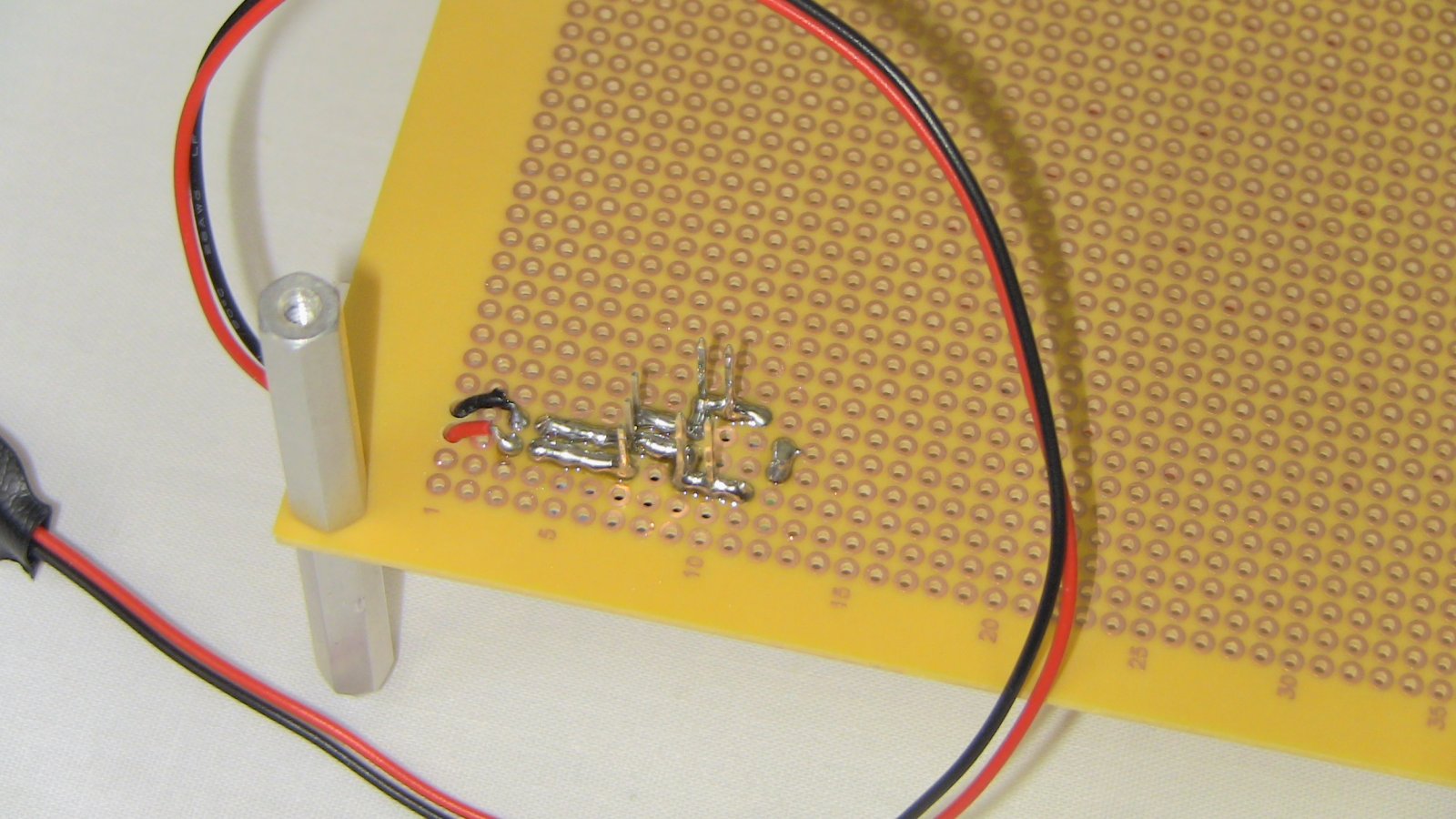
First, the power circuit is assembled and soldered to the board.
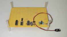
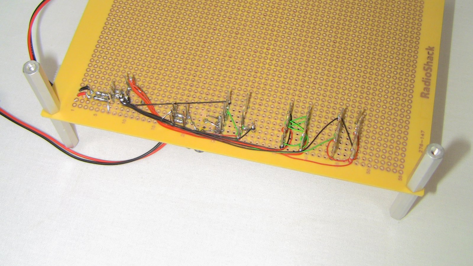
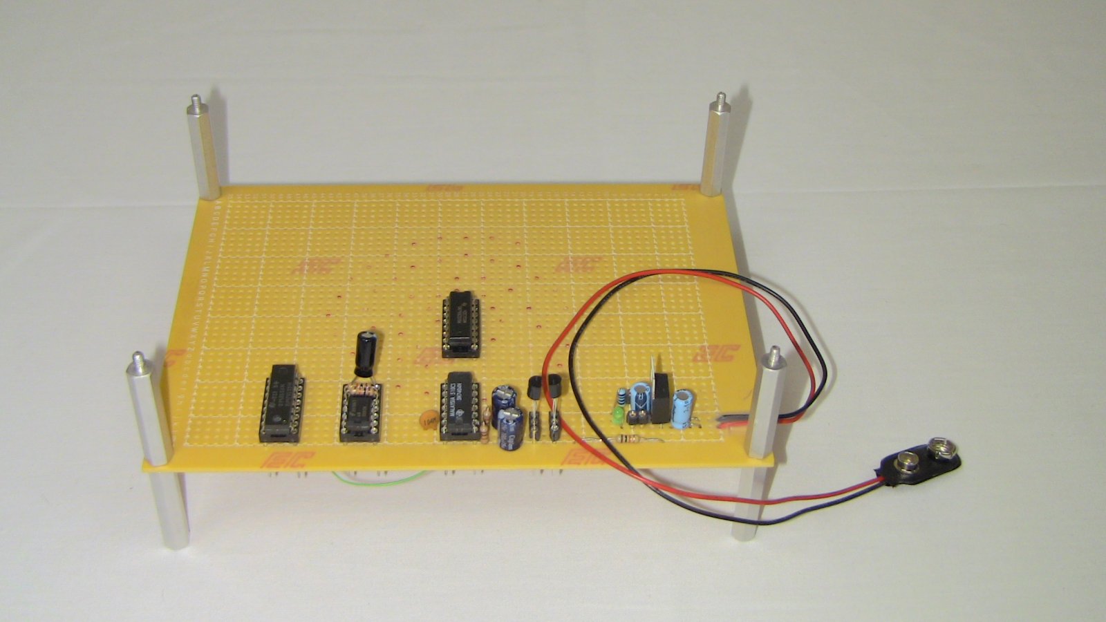
Next, the 555 timer circuit, counter circuit, and quasi-random pulse generator are connected!
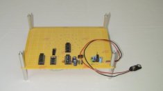
The first 74HC595 is added to the board and connected.
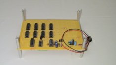
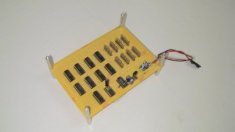
Then, all eight 74HC595 shift registers are connected to the circuit on the board.
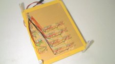
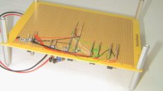
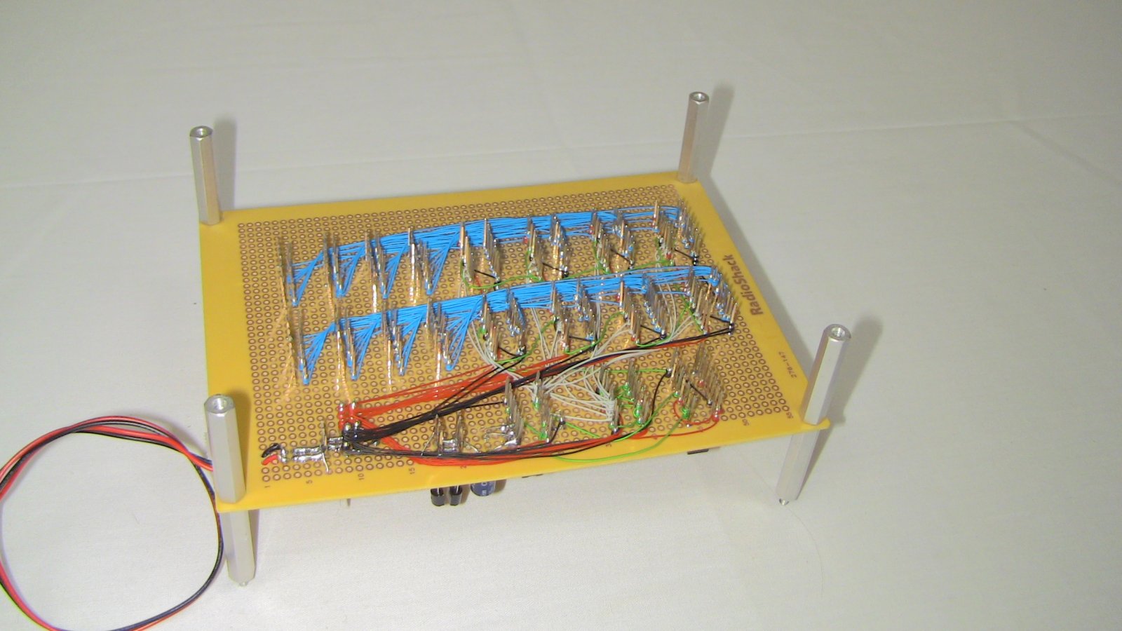
Now things get a bit harder: connecting the 74HC595's output to the 100 ohm resistors. There are smarter ways of doing this through soldering, but we like wire-wrapping and had a ton of blue wire-wrap that we never use.

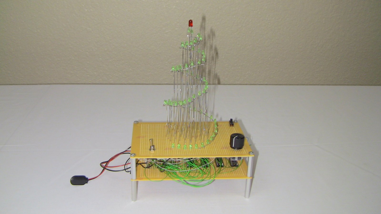
The last few things are connecting all of the 100 ohm resistors to the tree. We used green wire-wrap and you can see the bee's nest of wires in the photo below. Also, the switches and trimpot are added to the board.
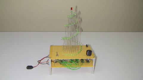
Now we'll add some labels, do some clean-up and give the system a test run to see how it works!
We're now on to the second part of the hardware design, the digital control! Since this project is all-hardware, no software, we get to use our hands building, soldering and wire-wrapping everything to make it work.
Building The LED Controller
First things first, gather all of the parts together from the parts list, including the LED Christmas tree we already built. We will follow the schematic from here on out.

First, the power circuit is assembled and soldered to the board.
Next, the 555 timer circuit, counter circuit, and quasi-random pulse generator are connected!

The first 74HC595 is added to the board and connected.

Then, all eight 74HC595 shift registers are connected to the circuit on the board.


Now things get a bit harder: connecting the 74HC595's output to the 100 ohm resistors. There are smarter ways of doing this through soldering, but we like wire-wrapping and had a ton of blue wire-wrap that we never use.

The last few things are connecting all of the 100 ohm resistors to the tree. We used green wire-wrap and you can see the bee's nest of wires in the photo below. Also, the switches and trimpot are added to the board.
Now we'll add some labels, do some clean-up and give the system a test run to see how it works!