The Shift Register
Since we're going to want the LEDs to turn on and off and flow all the way down the tree, a great solution is using shift registers. Wikipedia has a great page explaining Shift Registers, so feel free to check it out. Below is their example animation GIF showing data being written into a shift register and shifted out:

The shift register that we'll be using operates in a similar way to the animation seen above, except that each 74HC595 has 8 bits of output (we'll be driving 64 LEDs, so we'll need eight 74HC595's). In addition, we'll have two modes of input for what data should be shifted in: the mode where data input comes from the 555 timer and the mode where data input comes from the random pulse generator.
Quasi Random Pulse Generator
Since one of the modes we'll be operating in should spit out random pulses, we looked around for something that would do just that, and we came across a circuit like this:
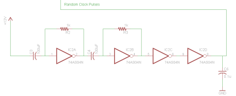
It's not truly random and actually fairly predictable; however, it's good enough for what we need, a non-pattern pulse generator that will make the LED Christmas tree look good with an alternate display mode. The circuit works by having to charge two caps in a certain sequence to be able to make any pulse come out of the final output. This means the pulse will follow the charge/discharge curve of the capacitors and depending on how much current is drawn each state transition, the capacitors will have to refill at some given rate.
Since we're going to want the LEDs to turn on and off and flow all the way down the tree, a great solution is using shift registers. Wikipedia has a great page explaining Shift Registers, so feel free to check it out. Below is their example animation GIF showing data being written into a shift register and shifted out:
The shift register that we'll be using operates in a similar way to the animation seen above, except that each 74HC595 has 8 bits of output (we'll be driving 64 LEDs, so we'll need eight 74HC595's). In addition, we'll have two modes of input for what data should be shifted in: the mode where data input comes from the 555 timer and the mode where data input comes from the random pulse generator.
Quasi Random Pulse Generator
Since one of the modes we'll be operating in should spit out random pulses, we looked around for something that would do just that, and we came across a circuit like this:
It's not truly random and actually fairly predictable; however, it's good enough for what we need, a non-pattern pulse generator that will make the LED Christmas tree look good with an alternate display mode. The circuit works by having to charge two caps in a certain sequence to be able to make any pulse come out of the final output. This means the pulse will follow the charge/discharge curve of the capacitors and depending on how much current is drawn each state transition, the capacitors will have to refill at some given rate.