Schematic Overview
Since this project is an all-hardware and no software project, the schematic is much bigger. Click on the image below to see the full-sized schematic:
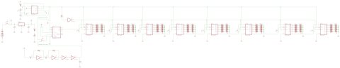
View Full Schematic
Schematic Specifics
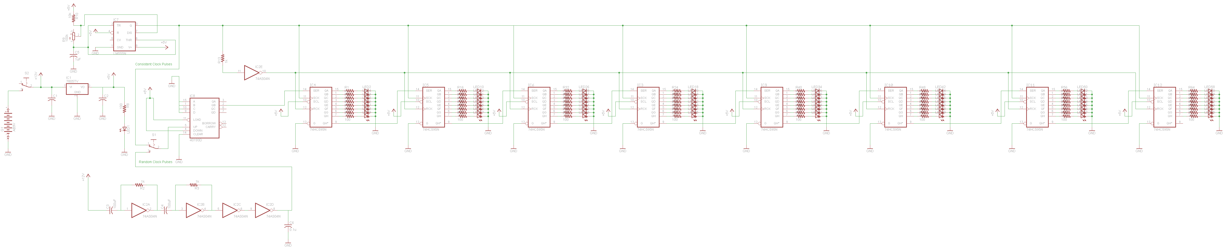
+5v Power Regulator and On/Off Toggle Switch
A 7805 +5v regulator is used for this project as everything here will be running off of +5v. The one exception is the random pulse generator, which is connected directly to the power supply input. So don't exceed +12v if you want this circuit to keep working in the future, you could damage something. We also added a power on/off toggle switch, which is a nice touch for keeping control of when the system is actually suppose to be on.
Mode Switch
The mode switch, changes between the pattern generator from the 555 and the quasi-random pulse generator from the 7404. This is a standard SPDT switch, or you could use two toggle switches if you wanted. The center pin is connected to the counter's input, and the outer two pins connect to the two different inputs: random pulse generator and 555 timer.
Shift Registers
8 shift registers all output to 8 LEDs through 100 ohm resistors. These ICs are why the schematic is so gigantic. A few pins need to be tied to ground or Vcc. It's usually better to use pull-up/pull-down resistors to do this, but I wanted to simplify the design down and so I sacrificed the extra current draw for a quicker and easier design.
Quasi-Random Pulse Generator
This circuitry is 4 hex inverters that feed into the mode switch for driving the data input on the very first 74HC595 shift register. The two capacitors connected to the first two hex inverter's charging and discharging is what makes this generator work.
Since this project is an all-hardware and no software project, the schematic is much bigger. Click on the image below to see the full-sized schematic:
View Full Schematic
Schematic Specifics
+5v Power Regulator and On/Off Toggle Switch
A 7805 +5v regulator is used for this project as everything here will be running off of +5v. The one exception is the random pulse generator, which is connected directly to the power supply input. So don't exceed +12v if you want this circuit to keep working in the future, you could damage something. We also added a power on/off toggle switch, which is a nice touch for keeping control of when the system is actually suppose to be on.
Mode Switch
The mode switch, changes between the pattern generator from the 555 and the quasi-random pulse generator from the 7404. This is a standard SPDT switch, or you could use two toggle switches if you wanted. The center pin is connected to the counter's input, and the outer two pins connect to the two different inputs: random pulse generator and 555 timer.
Shift Registers
8 shift registers all output to 8 LEDs through 100 ohm resistors. These ICs are why the schematic is so gigantic. A few pins need to be tied to ground or Vcc. It's usually better to use pull-up/pull-down resistors to do this, but I wanted to simplify the design down and so I sacrificed the extra current draw for a quicker and easier design.
Quasi-Random Pulse Generator
This circuitry is 4 hex inverters that feed into the mode switch for driving the data input on the very first 74HC595 shift register. The two capacitors connected to the first two hex inverter's charging and discharging is what makes this generator work.