State Machine Theory
The state machine for this project is simple at a glance, but can be confusing when you look into the details. First I'll explain the over-all view of what the states are and how they should be cycled through, then I'll explain further details of how the circuit should work when built.
The 3 States
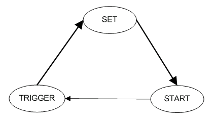
This system will have 3 states: [1] Set, [2] Start and [3] Trigger. The set state will change the output to the 74-192 counters so that the preset value of '25' will be loaded in. In the start state, the system will begin to down count by enabling the master clock to generate 1 Hz pulses. The Trigger state occurs when the value of 00 is reached, which will be denoted by the trigger LED turning on.
The SR FlipFlop
(Image Credit: Wikipedia)
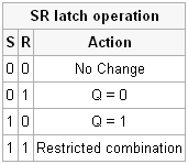
Two NOR gates form an SR flipflop as seen in the picture above. The SR flipflop changes state when a pulse is sent to the input of the active NOR gate yielding two possible states. Take a look at the SR flipflop truth table above, to get a better feeling for things.
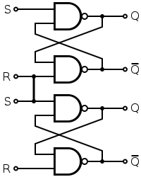
For this project, we want to have 3 states, not just 2 as a single SR flipflop offers. So we'll use two SR flipflops, connect them together (as seen above) and bingo, we have a simple 3 state machine.
The state machine for this project is simple at a glance, but can be confusing when you look into the details. First I'll explain the over-all view of what the states are and how they should be cycled through, then I'll explain further details of how the circuit should work when built.
This system will have 3 states: [1] Set, [2] Start and [3] Trigger. The set state will change the output to the 74-192 counters so that the preset value of '25' will be loaded in. In the start state, the system will begin to down count by enabling the master clock to generate 1 Hz pulses. The Trigger state occurs when the value of 00 is reached, which will be denoted by the trigger LED turning on.
(Image Credit: Wikipedia)
Two NOR gates form an SR flipflop as seen in the picture above. The SR flipflop changes state when a pulse is sent to the input of the active NOR gate yielding two possible states. Take a look at the SR flipflop truth table above, to get a better feeling for things.
For this project, we want to have 3 states, not just 2 as a single SR flipflop offers. So we'll use two SR flipflops, connect them together (as seen above) and bingo, we have a simple 3 state machine.