555 Timer Theory
The 555 timer is a wonder of the digital world because of its many uses in the digital domain. This project uses a dual 555 timer, which means there's actually two independent timers inside of a single IC. The first timer will be used as the master timer and the second for tone generation. Below, I will briefly discuss the designs we will use with these timers.
555 Tone Generation

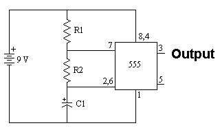
To generate the relatively high pitched 'beep' sound we need to build a circuit that outputs a constant frequency to drive a speaker. To do that we choose the 555 timer and use what has become a standard astable signal generating circuit (pictured above). We are shooting for around a 2~5 KHz output signal with no real accuracy, so I chose R1/R2 to be 10kΩ and C1 to be 10uF. You can mess around with these values to get higher or lower pitch, but the values I chose yield about a 4.5 KHz tone.
555 Master Clock

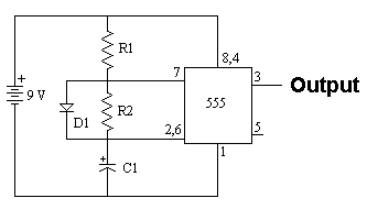
The master clock for this system needs to be designed more precisely than the tone generator because we want a frequency of about 1 Hz output and to make sure the duty cycle is lower, around 10%. To meet these requirements, the design is altered slightly by using a different R2 value and by adding a diode. The R2 value changes to 100kΩ yielding an output signal of ~1 Hz and when the diode is added across R2 the duty cycle becomes ~10%
The 555 timer is a wonder of the digital world because of its many uses in the digital domain. This project uses a dual 555 timer, which means there's actually two independent timers inside of a single IC. The first timer will be used as the master timer and the second for tone generation. Below, I will briefly discuss the designs we will use with these timers.
555 Tone Generation

To generate the relatively high pitched 'beep' sound we need to build a circuit that outputs a constant frequency to drive a speaker. To do that we choose the 555 timer and use what has become a standard astable signal generating circuit (pictured above). We are shooting for around a 2~5 KHz output signal with no real accuracy, so I chose R1/R2 to be 10kΩ and C1 to be 10uF. You can mess around with these values to get higher or lower pitch, but the values I chose yield about a 4.5 KHz tone.
555 Master Clock

The master clock for this system needs to be designed more precisely than the tone generator because we want a frequency of about 1 Hz output and to make sure the duty cycle is lower, around 10%. To meet these requirements, the design is altered slightly by using a different R2 value and by adding a diode. The R2 value changes to 100kΩ yielding an output signal of ~1 Hz and when the diode is added across R2 the duty cycle becomes ~10%