Hardware Design
Since we're using a breadboard for this project, that means we will need a lot of jumper wire to make all the connections. The following build procedure is how I did it, feel free to customize it to your breadboard size. Let's start building!
Building The Circuit
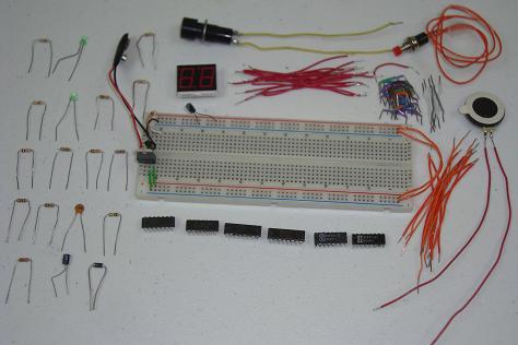
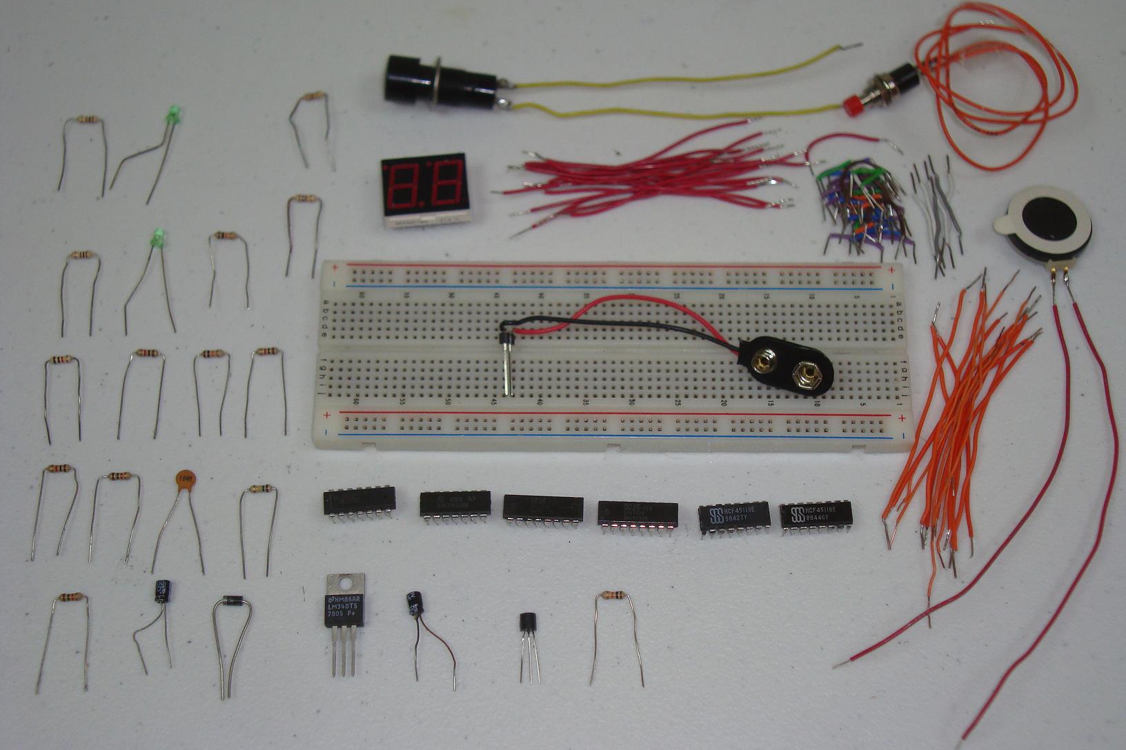
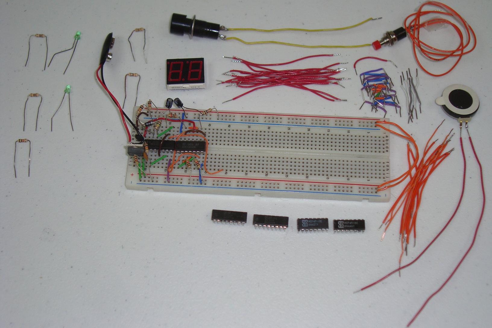
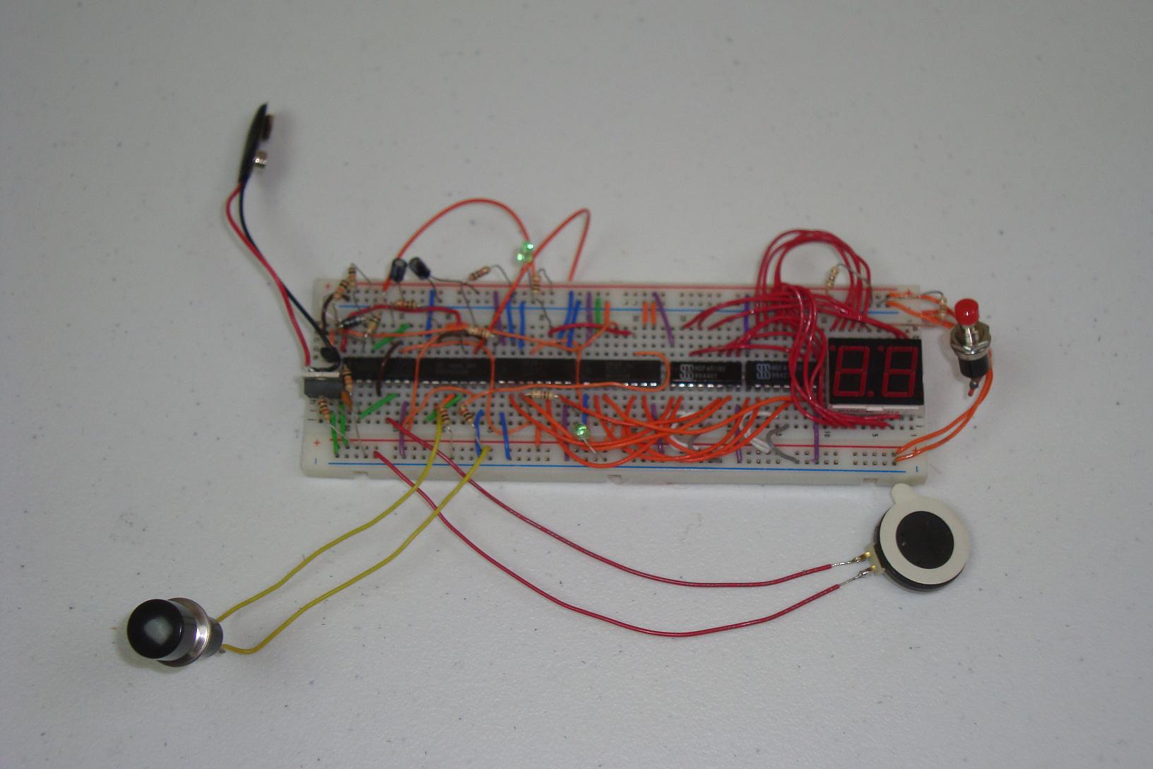
Get your parts together and follow the schematic. I built mine and in stages as you can see below...

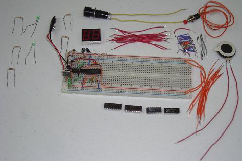
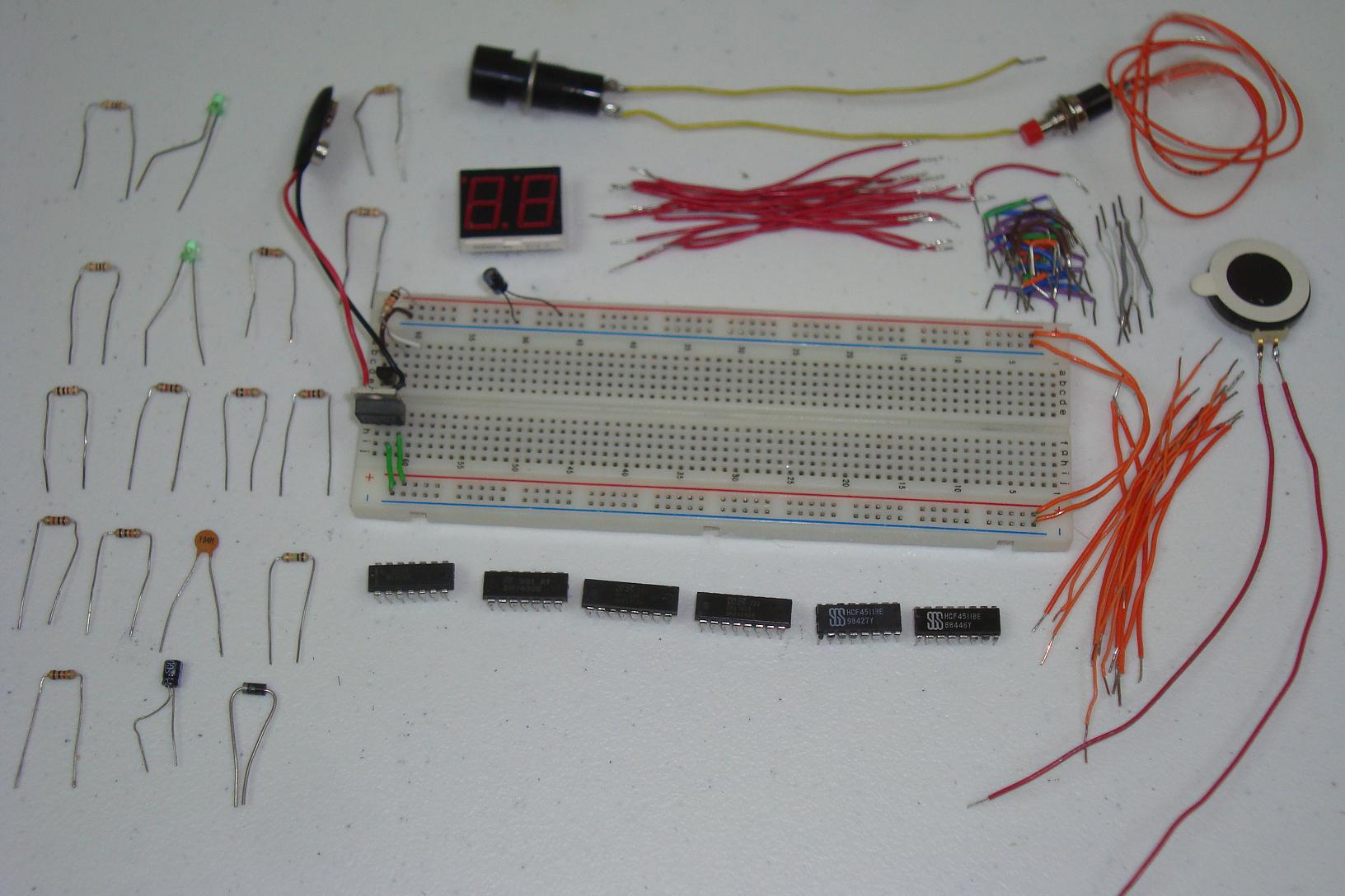
·First the power regulator circuit is connected on the breadboard along with the small 2n2222 circuit.
·The initial state machine and dual 555 timer circuit is assembled next.
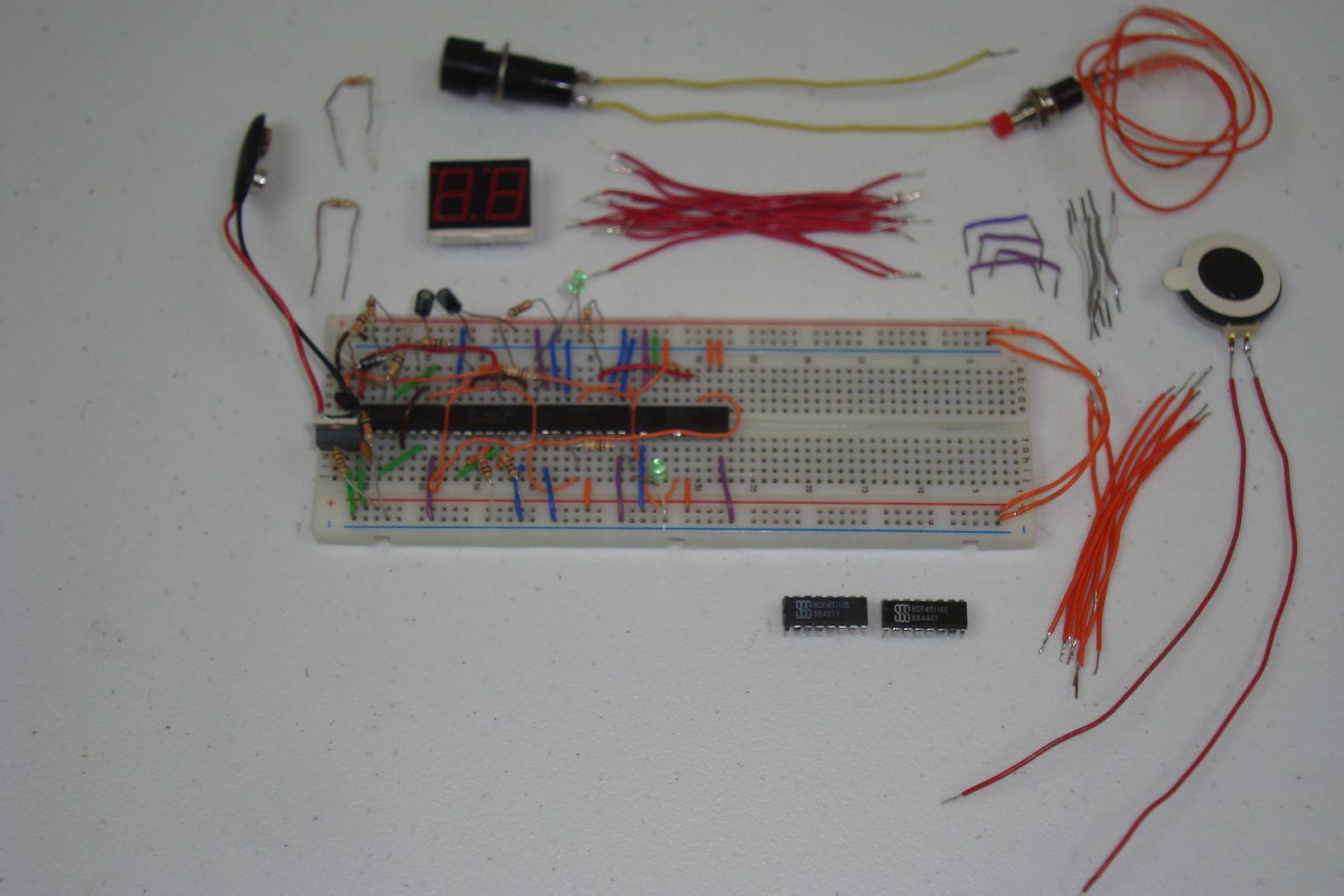
·The 74-192 4 bit decade counters are added and wired up.

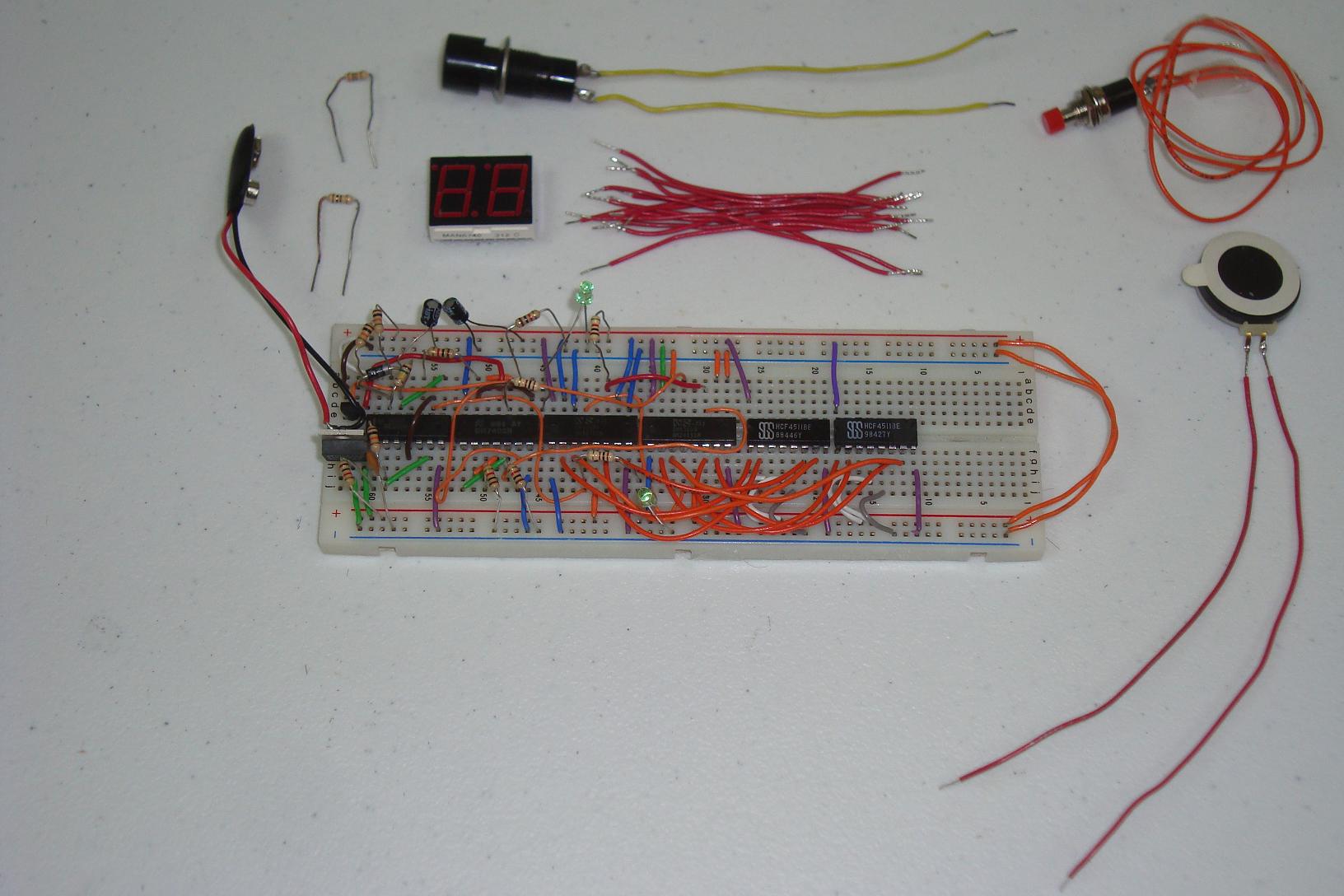
·Next, the 4511 LED drivers are added and connected to the 74-192's.

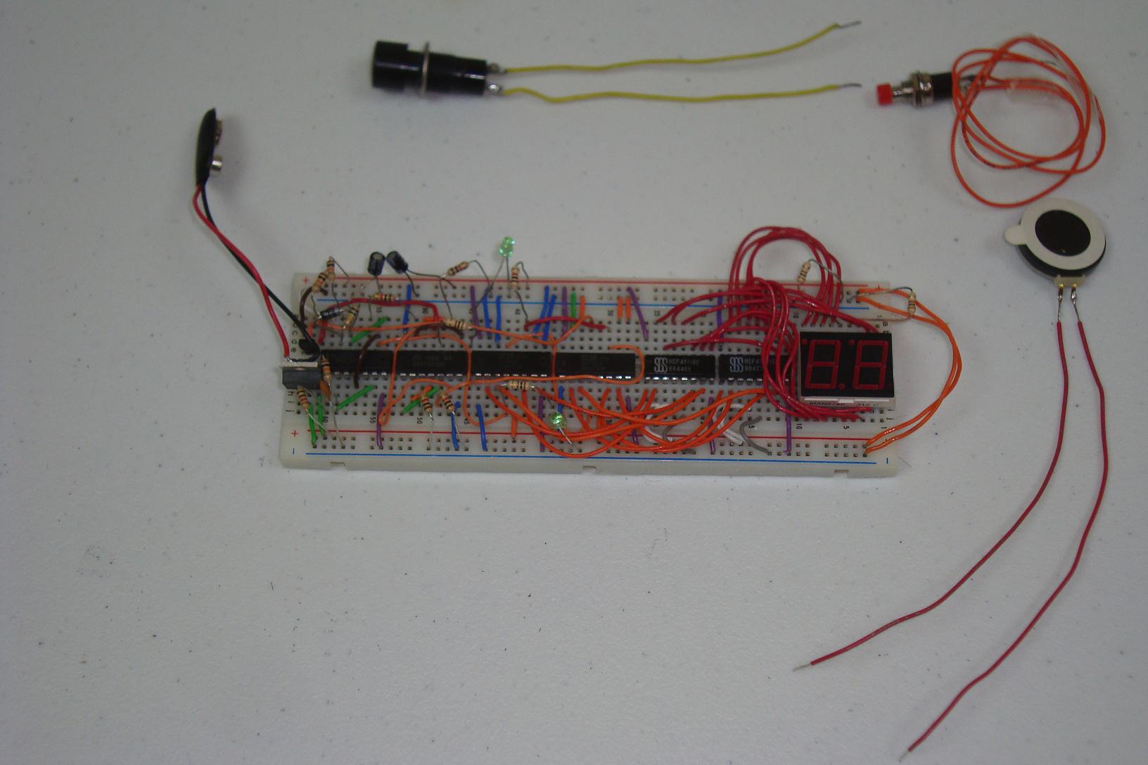
·Add the Dual 7 segment LED displays and connect them to the 4511 IC's.

·The last step is to add the push buttons and speaker.

·The pictures probably make it seem a lot easier to build than it really is. You should really wire up each section one at a time and test them to make sure they work as you're building. Do us all a favor and don't build the circuit up 100% and then start to debug it.
Since we're using a breadboard for this project, that means we will need a lot of jumper wire to make all the connections. The following build procedure is how I did it, feel free to customize it to your breadboard size. Let's start building!
Building The Circuit
Get your parts together and follow the schematic. I built mine and in stages as you can see below...
·First the power regulator circuit is connected on the breadboard along with the small 2n2222 circuit.
·The initial state machine and dual 555 timer circuit is assembled next.
·The 74-192 4 bit decade counters are added and wired up.
·Next, the 4511 LED drivers are added and connected to the 74-192's.
·Add the Dual 7 segment LED displays and connect them to the 4511 IC's.
·The last step is to add the push buttons and speaker.
·The pictures probably make it seem a lot easier to build than it really is. You should really wire up each section one at a time and test them to make sure they work as you're building. Do us all a favor and don't build the circuit up 100% and then start to debug it.