Assemble The PCB
Now that the PCB has been designed and built, we need to assemble all the parts onto it by using a soldering iron.
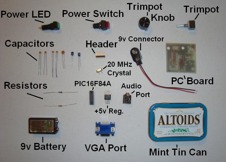
Below you can see all the parts that you will need for the PCB. They are labeled and you can always go back to the parts section to find where you can buy them.
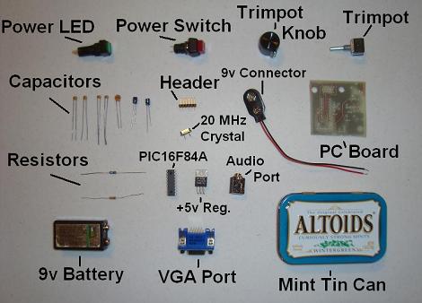
·Get all the parts out and ready to go.
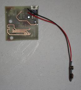

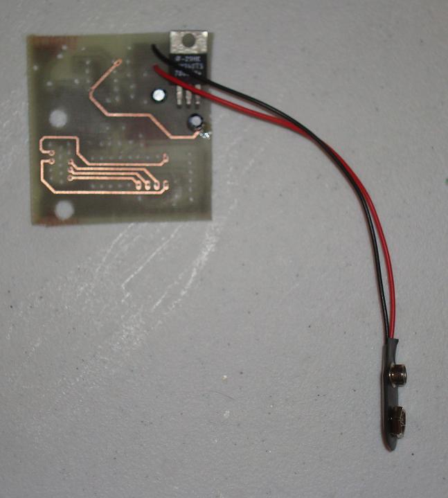
·First solder in the Power Circuitry, specifically the 7805 +5 Voltage Reg.
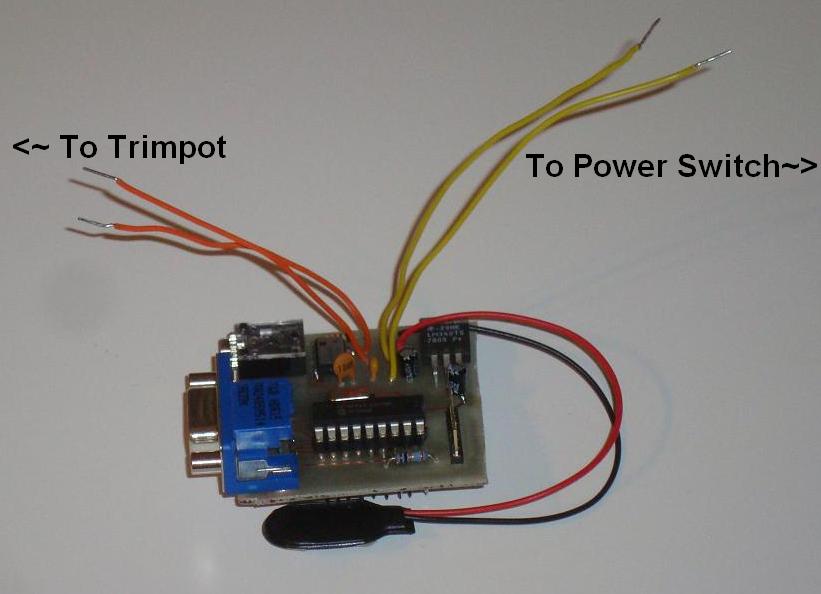
·Next solder in the Audio Circuitry. Use breadboard wire for the Trimpot and On/Off switch connections.
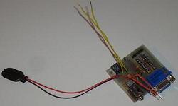
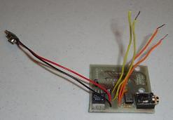
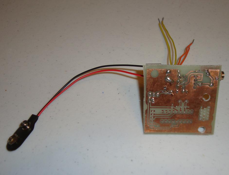
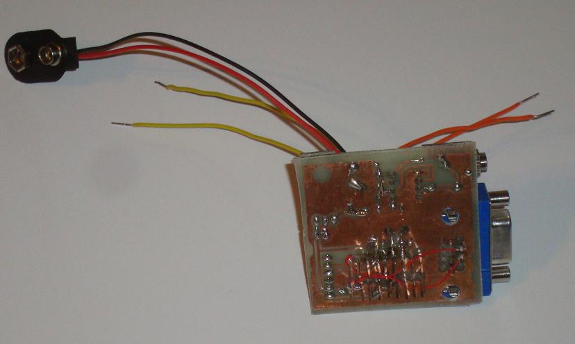
·Now solder in the Video Circuitry. Notice I used some SIPs for where the PIC 16F84A will go. This makes life easier if you ever have to remove the PIC. Also, I ended up adding some wire wrap for the Hsync and Vsync lines because it was too difficult to reach the solder points on the top side of the board...dumb design on my part.

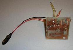
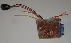
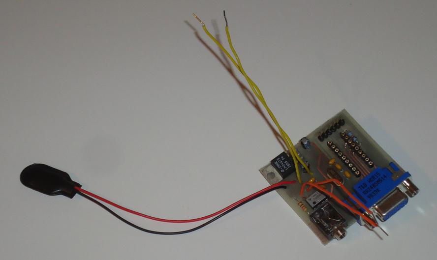
·Finally, we can see the completed PCB board with all parts on it. The 6 pin header is the programming port for the PIC, so when you're ready and you have the software compiled, you can download it to the PIC.
Now that the PCB has been designed and built, we need to assemble all the parts onto it by using a soldering iron.
Below you can see all the parts that you will need for the PCB. They are labeled and you can always go back to the parts section to find where you can buy them.
·Get all the parts out and ready to go.
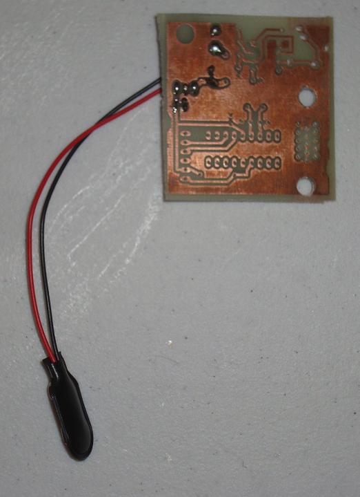
·First solder in the Power Circuitry, specifically the 7805 +5 Voltage Reg.
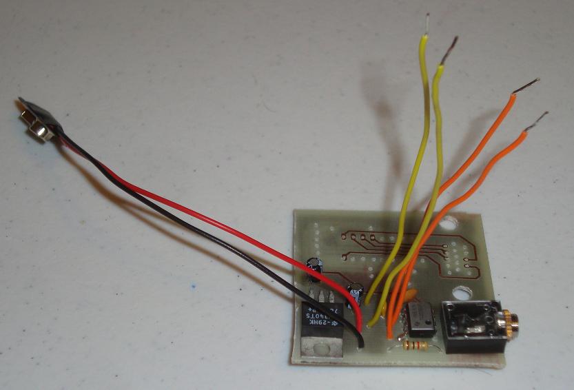
·Next solder in the Audio Circuitry. Use breadboard wire for the Trimpot and On/Off switch connections.
·Now solder in the Video Circuitry. Notice I used some SIPs for where the PIC 16F84A will go. This makes life easier if you ever have to remove the PIC. Also, I ended up adding some wire wrap for the Hsync and Vsync lines because it was too difficult to reach the solder points on the top side of the board...dumb design on my part.
·Finally, we can see the completed PCB board with all parts on it. The 6 pin header is the programming port for the PIC, so when you're ready and you have the software compiled, you can download it to the PIC.