Schematic Overview
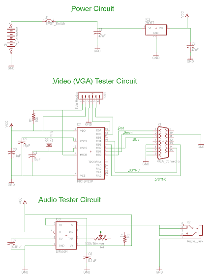
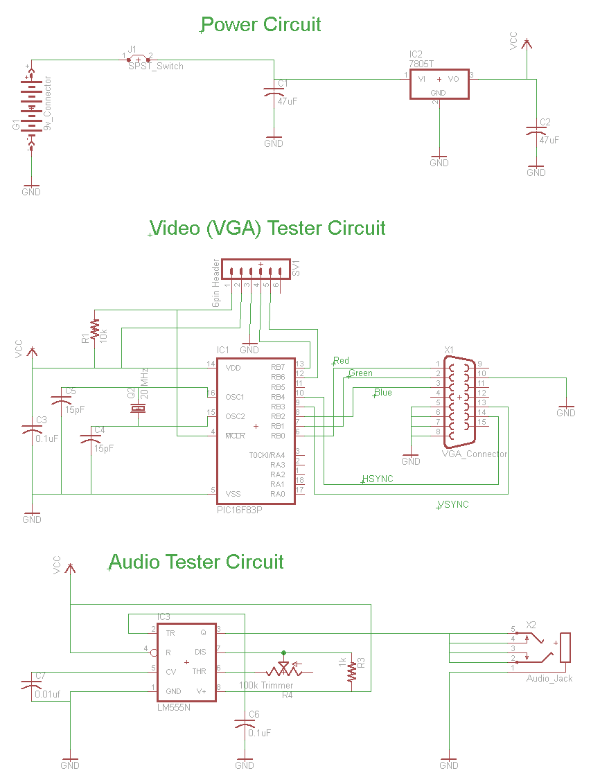
The Mini AV Test Box circuit is as simple and straight forward as I could design. It has three main sections that I split up in the schematic. The main devices used in the circuit are the 7805 +5v Regulator, 16F84A Microcontroller and 555 Timer.
View Full Schematic
Schematic Specifics
Power Circuit
This is a very standard small scale power circuit that uses a 7805 to regulate the +9v input down to +5v. There are 47uF DC filtering capacitors on the input and output signals to/from the 7805. These help to keep the voltage level stable which the other digital devices in the circuit want to see.
Video Test Circuit
The first portion of functional circuitry is for creating the VGA output signals. The PIC does that automatically on power-up. A second set of connections are made to a 6-pin header which can be used for both programming and debugging the PIC if necessary. This additional programming circuitry isn't necessary if you don't have to program your PIC 'on-board'.
Audio Test Circuit
This last portion of the schematic is where the Audio signal will be generated. The 555 timer is setup so that it will output tones from 70 Hz upto ear-piercing 14000 Hz, when the 100k trimpot is varied.